Mitsubishi Outlander XL. Manual - part 313


  Index      Mitsubishi     Mitsubishi Outlander XL - service repair manual 2007 year


Search            


Content   ..  311  312  313  314   ..


Mitsubishi Outlander XL. Manual - part 313


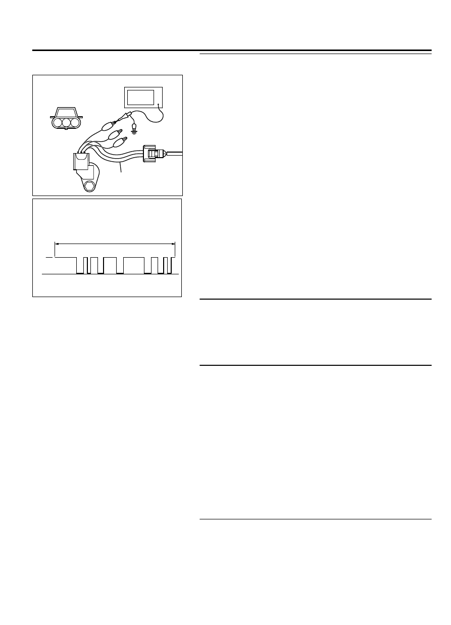
STEP 6. Using the oscilloscope, check the camshaft
position sensor.

ZK603389

3

2

1

AA00

Crankshaft position
sensor connector

Oscilloscope

MB991709

(1)

Disconnect the camshaft position sensor connector B-112,
and connect test harness special tool (MB991709) between
the  separated  connectors  (All  terminals  should  be
connected).

(2)

Connect  the  oscilloscope  probe  to  the  camshaft  position
sensor side connector terminal No. 3.

NOTE: 

When measuring with the ECM side connector,

disconnect all ECM connectors. Connect the check harness
special tool (MB992110) between the separated
connectors. then connector the oscilloscope probe to the
check harness connector terminal No. 14.

(3)

Start the engine and run at idle.

AA00

ZK603377

2 Engine revolutions

5V

Normal wavefome

(4)

Check the waveform.

The  waveform  should  show  a  pattern  similar  to  the
illustration.

(5)

Turn the ignition switch to the "LOCK" (OFF) position.

Q:Is the waveform normal?

YES:

 Go to Step 8.

NO:

 Go to Step 7.

STEP 7. Check the camshaft position sensing cylinder.

Q:Is  the  camshaft  position  sensing  cylinder  in  good

condition?

YES:

 Replace the camshaft position sensor. Then go to

Step 8.

NO:

 Repair it. Then go to Step 8.

STEP 8. Check the trouble symptoms.

(1)

Carry out a test drive with the drive cycle pattern. Refer to
Diagnostic  Function  -  OBD-II  Drive  Cycle  -  Pattern  24  P.
13B-6.

(2)

Check the diagnostic trouble code (DTC).

Q:Is DTC P0340 set?

YES:

 Replace the ECM. When the ECM is replaced, register

the ID code. Refer to GROUP 42B, ID Code Registration
Judgment Table <Vehicles with KOS> P.42B-12or GROUP
42C, ID Code Registration Judgment Table <Vehicles with
WCM> P.42C-8. Then go to Step 9.

NO:

 It can be assumed that this malfunction is

intermittent. Refer to GROUP 00, How to Use
Troubleshooting/Inspection Service Points - How to Cope
with Intermittent Malfunctions P.00-15.

STEP 9. Test the OBD-II drive cycle.

(1)

Carry out a test drive with the drive cycle pattern. Refer to
Diagnostic  Function  -  OBD-II  Drive  Cycle  -  Pattern  24  P.
13Ab-8.

MULTIPORT INJECTION SYSTEM (MFI) <DIAGNOSIS>

13Ab-447

DIAGNOSTIC TROUBLE CODE PROCEDURES

(2)

Check the diagnostic trouble code (DTC).

Q:Is DTC P0340 set?

YES:

 Retry the troubleshooting.

NO:

 The inspection is complete.

DTC P0401: Exhaust Gas Recirculation Flow Insufficient Detected

M11310100227USA0000010000

TECHNICAL DESCRIPTION

When  the  EGR  valve  (stepper  motor)  is  actuated
from  the  fully  closed  position  toward  the  open
position while the engine is running, EGR gas flows.

The  ECM  checks  how  the  EGR  gas  flow  signal
changes.

DESCRIPTIONS OF MONITOR METHODS

Small  manifold  pressure  change  during  exhaust
gas  recirculation  (EGR)  operation  from  closed  to
open.

MONITOR EXECUTION

Continuous

MONITOR EXECUTION CONDITIONS (Other
monitor and Sensor)

Other Monitor (There is no temporary DTC stored in
memory for the item monitored below)

EGR stepper motor monitor

Sensor (The sensor below is determined to be
normal)

Mass airflow sensor

Engine coolant temperature sensor

Intake air temperature sensor

Barometric pressure sensor

Throttle position sensor

Manifold absolute pressure sensor

Accelerator pedal position sensor

13Ab-448

MULTIPORT INJECTION SYSTEM (MFI) <DIAGNOSIS>

DIAGNOSTIC TROUBLE CODE PROCEDURES

DTC SET CONDITIONS

Logic Flow Chart

No

No

No

Yes

Yes

Yes

AK603766

P0


: Threshold  valu e

AA00

Nm = 0

Good

Malfunction

Monitoring

conditions

Nm = 3

P2 - P1 < P0 *

Nm = 0

Nm = Nm + 1

End

Measure manifold

pressure (P1)

EGR valve open

(1.0sec)

Measure manifold

pressure (P2)

Start

Check Conditions

At  least  20  seconds  have  passed  since  the  last
monitor was complete.

Engine  coolant  temperature  is  higher  than  76°C
(169°F).

Engine speed is at between 960 and 1,500 r/min.

Intake air temperature is higher than -10°C (14°F).

MULTIPORT INJECTION SYSTEM (MFI) <DIAGNOSIS>

13Ab-449

DIAGNOSTIC TROUBLE CODE PROCEDURES

Barometric  pressure  is  higher  than  76  kPa  (22.4
in.Hg).

Vehicle speed is 30 km/h (19 mph) or more.

At  least  90  seconds  have  passed  since  manifold
absolute pressure sensor output voltage fluctuated
1.5 volts or more.

Battery positive voltage is higher than 10.3 volts.

The throttle valve is closed.

Volumetric efficiency is lower than 22 percent.

The PCM monitors for this condition for 3 cycles of
1.8 seconds each during the drive cycle.

Judgement Criterion

When  the  EGR  valve  opens  to  the  prescribed
opening, when intake manifold pressure fluctuation
width is lower than 2.0 kPa (0.59 in.Hg).

OBD-II DRIVE CYCLE PATTERN
Refer to Diagnostic Function - OBD-II Drive Cycle -
Pattern 3 P.13Ab-8.

TROUBLESHOOTING HINTS (The most likely
causes for this code to be set are: )

EGR valve (stepper motor) failed.

Open or shorted EGR valve (stepper motor) circuit,
or connector damage.

Manifold absolute pressure sensor failed.

ECM failed.


DIAGNOSIS

Required Special Tools:

MB991958: Scan Tool (M.U.T.-III Sub Assembly)

MB991824: V.C.I.

MB991827: USB Cable

MB991910: Main Harness A

STEP 1. Using scan tool MB991958, check data list item 8:
Manifold Absolute Pressure Sensor.

ZC501967

AC404789

ZC5019680000

MB991824

MB991827

MB991910

Data link

connector

To prevent damage to scan tool MB991958, always turn the
ignition  switch  to  the  "LOCK"  (OFF)  position  before
connecting or disconnecting scan tool MB991958.

(1)

Connect scan tool MB991958 to the data link connector.

(2)

Start the engine and run at idle.

(3)

Set scan tool MB991958 to the data reading mode for item
8, Manifold Absolute Pressure Sensor.

(4)

Warm up the engine to normal operating temperature: 80°C
to 95°C (176°F to 203°F).

Should be between 16 - 36 kPa (4.7 - 10.6 in.Hg) at engine
idling.

(5)

Turn the ignition switch to the "LOCK" (OFF) position.

Q:Is the sensor operating properly?

YES:

 Clean the EGR valve and EGR passage. Then go to Step

2.

NO:

 Refer to DTC P0106 - Manifold Absolute Pressure

Sensor Circuit Range/Performance Problem P.13Ab-126, DTC
P0107 - Manifold Absolute Pressure Sensor Circuit Low
Input P.13Ab-132, DTC P0108 - Manifold Absolute Pressure
Sensor Circuit High Input P.13Ab-138.

STEP 2. Check the EGR system
Refer to GROUP 17, Emission Control System - Exhaust Gas
Recirculation (EGR) System - General Information P.17c-13.

13Ab-450

MULTIPORT INJECTION SYSTEM (MFI) <DIAGNOSIS>

DIAGNOSTIC TROUBLE CODE PROCEDURES


Content   ..  311  312  313  314   ..