Mitsubishi Outlander XL. Manual - part 285


  Index      Mitsubishi     Mitsubishi Outlander XL - service repair manual 2007 year


Search            


Content   ..  283  284  285  286   ..


Mitsubishi Outlander XL. Manual - part 285


DTC SET CONDITIONS <Circuit continuity - shorted high>
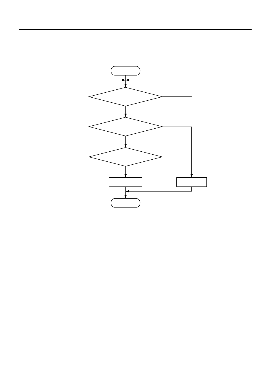
Logic Flow Chart

Start

End

No

Yes

Yes

Yes

No

No

Malfunction

Good

Continuous

failure for 2secs

Current >= 4A

Monitoring

conditions

ZK603736 AA00

Check Condition

Engine is running.

Judgement Criterion

The coil current is 4 ampere or more with the injector
driving.

OBD-II DRIVE CYCLE PATTERN

Refer to Diagnostic Function - OBD-II Drive Cycle -
Pattern 24 P.13Ab-8.

TROUBLESHOOTING HINTS (The most likely
causes for this code to be set are:)

No. 1 cylinder injector failed.

Connector damage.

Harness damage.

ECM failed.


DIAGNOSIS

Required Special Tools:

MB991958: Scan Tool (M.U.T.-III Sub Assembly)

MB991824: V.C.I.

MULTIPORT INJECTION SYSTEM (MFI) <DIAGNOSIS>

13Ab-335

DIAGNOSTIC TROUBLE CODE PROCEDURES

MB991827: USB Cable

MB991910: Main Harness A

MB991658: Test Harness

MB992110: Power Plant ECU Check Harness

STEP 1. Using scan tool MB991958, check actuator test item
1: No. 1 Injector.

ZC501967

AC404789

ZC5019680000

MB991824

MB991827

MB991910

Data link

connector

To prevent damage to scan tool MB991958, always turn the
ignition  switch  to  the  "LOCK"  (OFF)  position  before
connecting or disconnecting scan tool MB991958.

(1)

Connect scan tool MB991958 to the data link connector.

(2)

Start the engine and run at idle.

(3)

Set scan tool MB991958 to the actuator testing mode for item
1, No. 1 injector.

(4)

Warm up the engine to normal operating temperature: 80°C
to 95°C (176°F to 203°F).

The idle should become slightly rougher.

(5)

Turn the ignition switch to the "LOCK" (OFF) position.

Q:Is the actuator operating properly?

YES:

 It can be assumed that this malfunction is

intermittent. Refer to GROUP 00, How to Use
Troubleshooting/Inspection Service Points - How to Cope
with Intermittent Malfunctions P.00-15.

NO:

 Go to Step 2.

STEP 2. Check for harness connector B- 21 at the
intermediate connector and B-10 at the ECM for damage.

Q:Is the harness connector in good condition?

YES:

 Go to Step 3.

NO:

 Repair it. Refer to GROUP 00E, Harness Connector

Inspection P.00E-2. Then go to Step 10.

STEP 3. Measure the injector supply voltage at the
intermediate connector harness B-21 and ground.

3

4

5

8

9

1

2

6

7

10

ZK603326

B-21 Harness
connector:
harness side

AA00

(1)

Disconnect the intermediate connector B-21 and measure at
the female connector side.

(2)

Turn the ignition switch to the "ON" position.

(3)

Measure the voltage between terminal No. 6 and ground.

Voltage should be battery positive voltage.

(4)

Turn the ignition switch to the "LOCK" (OFF) position.

Q:Is the measured resistance battery positive voltage?

YES:

 Go to Step 5.

NO:

 Go to Step 4.

13Ab-336

MULTIPORT INJECTION SYSTEM (MFI) <DIAGNOSIS>

DIAGNOSTIC TROUBLE CODE PROCEDURES

STEP 4. Check for harness between the injector relay
connector A-24X and the intermediate connector B-21.

2

1

3
4

1

2

3

4

5

6

7

8

9

10

ZK603327

A-24X Harness
connector:
component side

B-21 Harness
connector:
component side

AA00

(1)

Disconnect  the  injector  relay  connector  A-24X  and  the
intermediate connector B-21.

(2)

Measure  the  resistance  injector  relay  connector  A-24X
(terminal  No.  3)  and  the  intermediate  connector  B-21
(terminal No. 6).

Should be less than 2 ohms.

Q:Is the harness wire in good condition?

YES:

 Go to Step 9.

NO:

 Repair it. Then go to Step 10.

STEP 5. Check the No. 1 cylinder injector resistance at
intermediate connector B-21.

(1)

Disconnect the intermediate connector B-21 and measure at
male connector side.

5

4

3

2

1

10

9

8

7

6

ZK603328

B-21 
Intermediate
connector

AA00

(2)

Measure the resistance between terminal No. 6 and No. 7.

Resistance should be between 10.5 and 13.5 ohms.

Q:Is the measured resistance between 10.5 and 13.5 ohms?

YES:

 Go to Step 8.

NO:

 Go to Step 6.

STEP 6. Check the harness connector B-101 at No. 1
cylinder injector for damage.
Remove the intake manifold.

Q:Is the harness connector in good condition?

YES:

 Go to Step 7.

NO:

 Repair it. Refer to GROUP 00E, Harness Connector

Inspection P.00E-2. Then go to Step 10.

STEP 7. Check the No. 1 cylinder injector B-101.

(1)

Disconnect the No. 1 cylinder injector connector B-101.

MULTIPORT INJECTION SYSTEM (MFI) <DIAGNOSIS>

13Ab-337

DIAGNOSTIC TROUBLE CODE PROCEDURES

ZK603186AA00

Injector side
connector

1 2

(2)

Measure  the  resistance  between  injector  side  connector
terminal No. 1 and No. 2.

Standard value: 10.5 - 13.5 ohms [at 20°C (68°F)]

Q:Is the measured resistance between 10.5 and 13.5 ohms

[at 20°C (68°F)]?

YES:


Repair  harness  wire  between  the  intermediate  connector
B-21  (terminal  No.  6)  and  the  injector  connector  B-101
(terminal  No.  1)  and  harness  wire  between  injector
connector  B-101  (terminal  No.  2)  and  intermediate
connector B-21 (terminal No. 7) because of open circuit or
short circuit to ground or harness damage.
Then go to Step 10.

NO:

 Replace the No. 1 cylinder injector. Then go to Step

10.

STEP 8. Check for harness between the intermediate
connector B-21and the ECM connector B-10.

(1)

Disconnect  the  intermediate  connector  B-21  and  the  ECM
connector B-10.

(2)

Measure the resistance between the intermediate connector
B-21 (terminal No. 7) and the ECM connector B-10 (terminal
No. 2).

Should be less than 2 ohms.

B-21 Harness
connector:
component side

AA00

ZK603329

1

2

3

4

5

6

7

8

9

10

(3)

Measure the continuity between the intermediate connector
B-21 (terminal No. 7) and ground.

Not continuity

Q:Is the harness wire in good condition?

YES:

 Go to Step 9.

NO:

 Repair it. Refer to GROUP 00E, Harness Connector

Inspection P.13Aa-17. Then go to Step 10.

STEP 9. Using the oscilloscope, check the No. 1 cylinder
injector.

(1)

Disconnect the intermediate connector B-21 and connect the
test harness MB991658 between the separated connectors.

B-21 Intermediate
connector

MB991658

Oscilloscope

5

4

3

2

1

10

9

8

7

6

AA00

ZK603330

(2)

Connect  the  oscilloscope  probe  to  injector  intermediate
connector terminal to No. 7.

NOTE: 

When measuring with the ECM side connector,

disconnect all ECM connectors. Connect the check harness
special tool (MB992110) between the separated
connectors. Then connect an oscilloscope probe to the
check harness connector terminal No. 2.

(3)

Start the engine and run at idle.

13Ab-338

MULTIPORT INJECTION SYSTEM (MFI) <DIAGNOSIS>

DIAGNOSTIC TROUBLE CODE PROCEDURES


Content   ..  283  284  285  286   ..