Mitsubishi Outlander XL. Manual - part 276


  Index      Mitsubishi     Mitsubishi Outlander XL - service repair manual 2007 year


Search            


Content   ..  274  275  276  277   ..


Mitsubishi Outlander XL. Manual - part 276


ZK604078

M

1

2

16

15 14 13 12 11 10 9 8 7 6 5 4 3

2

1

32

31 30 29 28 27 26 25 24 23 22 21 20 19 18

17

48

47 46 45 44 43 42 41 40 39 38 37 36 35 34

33

64

63 62 61 60 59 58 57 56 55 54 53 52 51 50

49

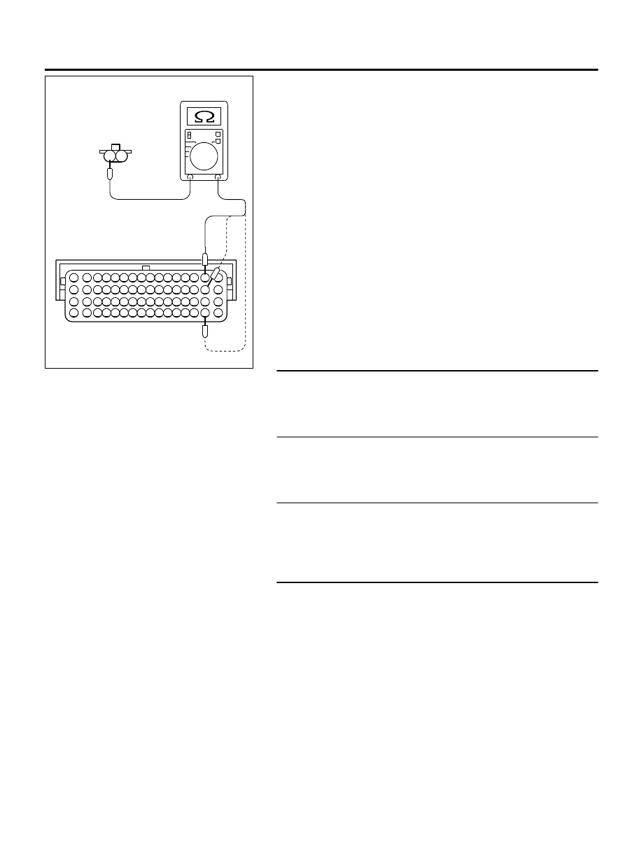
B-101, B-103, B-104,
harness connector:
component side 

AA00

B-10 Harness
connector:
component side 

(3)

Measure  the  resistance  between  the  right  bank  injector
connector  B-101,  B-103,  B-104  and  the  ECM  connector
B-10.

  a

.

Connector  B-101  (terminal  No.  2)  and  connector  B-10
(terminal No. 2) at No. 1 cylinder injector.

b
.

Connector  B-103  (terminal  No.  2)  and  connector  B-10
(terminal No. 18) at No. 3 cylinder injector.

c
.

Connector  B-104  (terminal  No.  2)  and  connector  B-10
(terminal No.50) at No. 5 cylinder injector.

Should be less than 2 ohms.

Q:Is the harness wire in good condition?

YES:

 Go to Step 12.

NO:

 Repair or replace it. Refer to GROUP 00E, Harness

Connector Inspection P.00E-2. Then go to Step 16.

STEP 12. Check for exhaust leaks.

Q:Are there any abnormalities?

YES:

 Repair it. Then go to Step 16.

NO:

 Go to Step 13.

STEP 13. Check for intake system vacuum leak.

Q:Are there any abnormalities?

YES:

 Repair it. Then go to Step 16.

NO:

 Go to Step 14.

STEP 14. Check for entry of foreign matter (water, kerosene,
etc.) into fuel.

Q:Are there any abnormalities?

YES:

 Replace the fuel. Then go to Step 16.

NO:

 Go to Step 15.

STEP 15. Replace the right bank injector.

(1)

Replace the right bank injector.

(2)

Carry out a test drive with the drive cycle pattern. Refer to
Diagnostic  Function  -  OBD-II  Drive  Cycle  -  Pattern  22  P.
13Ab-8.

(3)

Check the diagnostic trouble code (DTC).

Q:Is DTC P0171 set?

YES:

 Replace the ECM. When the ECM is replaced, register

the ID code. Refer to GROUP 42B, ID Code Registration
Judgment Table <Vehicles with KOS> P.42B-12or GROUP
42C, ID Code Registration Judgment Table <Vehicles with
WCM> P.42C-8. Then go to Step 16.

NO:

 The inspection is complete.

MULTIPORT INJECTION SYSTEM (MFI) <DIAGNOSIS>

13Ab-299

DIAGNOSTIC TROUBLE CODE PROCEDURES

STEP 16. Test the OBD-II drive cycle.

(1)

Carry out a test drive with the drive cycle pattern. Refer to
Diagnostic  Function  -  OBD-II  Drive  Cycle  -  Pattern  22  P.
13Ab-8.

(2)

Check the diagnostic trouble code (DTC).

Q:Is DTC P0171 set?

YES:

 Retry the troubleshooting.

NO:

 The inspection is complete.

DTC P0172: System too Rich (bank 1)

M11310100203USA0000010000

Fuel Trim Circuit

Refer to DTC P0201- Injector Circuit - Cylinder 1 P.
13Ab-332, 
 P0203-  Injector  Circuit  -  Cylinder  3  P.
13Ab-347, 
 P0205-  Injector  Circuit  -  Cylinder  5  P.
13Ab-362.

CIRCUIT OPERATION

Refer to DTC P0201- Injector Circuit - Cylinder 1 P.
13Ab-332, 
 P0203-  Injector  Circuit  -  Cylinder  3  P.
13Ab-347, 
 P0205-  Injector  Circuit  -  Cylinder  5  P.
13Ab-362.

TECHNICAL DESCRIPTION

If a malfunction occurs in the fuel system, the fuel
trim value becomes too small.

The  ECM  checks  whether  the  fuel  trim  value  is
within a specified range.

DESCRIPTIONS OF MONITOR METHODS
Right bank air/fuel learning value (long time fuel trim)
and  air/fuel  feedback  integral  value  (short  time  fuel
trim) are too rich.

MONITOR EXECUTION

Continuous

MONITOR EXECUTION CONDITIONS (Other
monitor and Sensor)

Other Monitor (There is no temporary DTC stored in
memory for the item monitored below)

Misfire monitor

Sensor (The sensor below is determined to be
normal)

Mass airflow sensor

Engine coolant temperature sensor

Intake air temperature sensor

Barometric pressure sensor

Throttle position sensor

13Ab-300

MULTIPORT INJECTION SYSTEM (MFI) <DIAGNOSIS>

DIAGNOSTIC TROUBLE CODE PROCEDURES

DTC SET CONDITIONS

Logic Flow Chart

K

L rn

: Long-te rm  trim

K

I

: Sho rt-te rm  trim

K0

: Maxi m um  limit  of  long-te rm  trim

K1

: Maxi m um  limit  of  sho rt-te rm  trim

K2

: Mini m um  limit  of  long-te rm  trim

K3

: Mini m um  limit  of  sho rt-te rm  trim

Start

Monitoring

conditions

End

No

No

No

No

No

No

Yes

Yes

Yes

Yes

Yes

Yes

K

L rn

> K0

Malfunction

Good

K

L rn

< K

2

K

I

< K

3

K

I

> K

1

Conti nuous  failur e

for  2sec s

ZK603728 AA00

Check Conditions

Under the closed loop air/fuel ratio control.

Engine  coolant  temperature  is  higher  than  76°C
(169°F).

Mass airflow sensor output is 12 g/sec or more.

Judgement Criterion

Long-term fuel trim has continued to be lower than
-12.5 percent for 5 seconds.

or

Short-term fuel trim has continued to be lower than
-7.4 percent for 5 seconds.

Check Conditions

Under the closed loop air/fuel ratio control.

Engine  coolant  temperature  is  higher  than  76°C
(169°F).

Mass airflow sensor output is 12 g/sec or less.

Judgement Criterion

Long-term fuel trim has continued to be lower than
-12.5 percent for 5 seconds.

MULTIPORT INJECTION SYSTEM (MFI) <DIAGNOSIS>

13Ab-301

DIAGNOSTIC TROUBLE CODE PROCEDURES

or

Short-term fuel trim has continued to be lower than
-12.5 percent for 5 seconds.

Check Conditions

Engine  coolant  temperature  is  higher  than  76°C
(169°F).

Under the closed loop air/fuel ratio control.

Judgement Criterion

Long-term  fuel  trim  has  continued  to  be  -12.5
percent for 2 seconds.

or

Short-term  fuel  trim  has  continued  to  be  -50.0
percent for 2 seconds.

OBD-II DRIVE CYCLE PATTERN

Refer to Diagnostic Function - OBD-II Drive Cycle -
Pattern 22 P.13Ab-8.

TROUBLESHOOTING HINTS (The most likely
causes for this code to be set are:)

Mass airflow sensor failed.

Injector (Number 1, 3, 5) failed.

Incorrect fuel pressure.

Engine coolant temperature sensor failed.

Intake air temperature sensor failed.

Manifold absolute pressure sensor failed.

ECM failed.


DIAGNOSIS

Required Special Tools:

MB991958: Scan Tool (M.U.T.-III Sub Assembly)

MB991824: V.C.I.

MB991827: USB Cable

MB991910: Main Harness A

STEP 1. Using scan tool MB991958, check data list item 10:
Mass Airflow Sensor.

ZC501967

AC404789

ZC5019680000

MB991824

MB991827

MB991910

Data link

connector

To prevent damage to scan tool MB991958, always turn the
ignition  switch  to  the  "LOCK"  (OFF)  position  before
connecting or disconnecting scan tool MB991958.

(1)

Connect scan tool MB991958 to the data link connector.

(2)

Start the engine and run at idle.

(3)

Set scan tool MB991958 to the data reading mode for item
10, Mass Airflow Sensor.

(4)

Warm up the engine to normal operating temperature: 80°C
to 95°C (176°F to 203°F).

When idling, between 1,350 and 1,670 millivolts.

When 2,500 r/min, between 1,620 and 2,020 millivolts.

(5)

Turn the ignition switch to the "LOCK" (OFF) position.

Q:Is the sensor operating properly?

YES:

 Go to Step 2.

NO:

 Refer to DTC P0101 - Mass Airflow Circuit Range/

Performance Problem P.13Ab-108, DTC P0102 - Mass Airflow
Circuit Low Input P.13Ab-115, DTC P0103 - Mass Airflow
Circuit High Input P.13Ab-121.

STEP 2. Using scan tool MB991958, check data list item 5:
Intake Air Temperature Sensor.

(1)

Turn the ignition switch to the "ON" position.

(2)

Set scan tool MB991958 to the data reading mode for item
5, Intake Air Temperature Sensor.

13Ab-302

MULTIPORT INJECTION SYSTEM (MFI) <DIAGNOSIS>

DIAGNOSTIC TROUBLE CODE PROCEDURES


Content   ..  274  275  276  277   ..