Mitsubishi Outlander XL. Manual - part 274
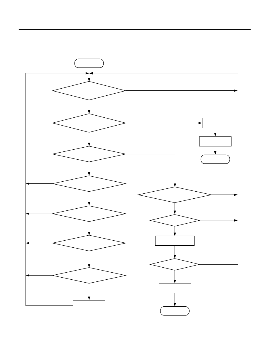
DTC SET CONDITION
Logic Flow Chart
Yes
Yes
No
No
No
No
No
No
No
Monitoring
condition
Yes
Yes
Yes
F1 = 1
F1 = 1
F2 = F2 + 1, F1 = 0
F1 = F2 = 0
Good
Continuous fuel cut > 2secs
Vehicle speed > 30km/h
Vehicle speed < 1.5m/h
Yes
Yes
ZK603721AA00
Engine speed > 1500rpm
End
End
Start
F2 >= 3
Malfunction
Yes
Yes
Load valve > 40%
No
Have 10secs passed?
Yes
No
No
Output voltage
change < 0.313V
MULTIPORT INJECTION SYSTEM (MFI) <DIAGNOSIS>
13Ab-291
DIAGNOSTIC TROUBLE CODE PROCEDURES