Mitsubishi Outlander XL. Manual - part 197


  Index      Mitsubishi     Mitsubishi Outlander XL - service repair manual 2007 year


Search            


Content   ..  195  196  197  198   ..


Mitsubishi Outlander XL. Manual - part 197


1 2 3 4

5 6 7

8 9 10 11

131415

12

1 2

1 2

1

6

4

5

9

8

10 11

13

15

14

12

16

7

2 3

ZK602048

<Battery voltage is supplied>

AA00

Etacs-ECU side connector

Connector “D”

Connector “C”

Connector “B”

Connector “A”

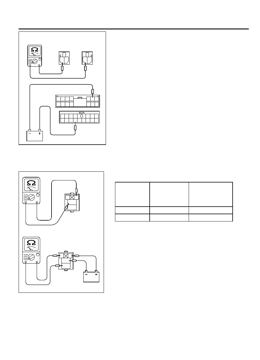
INJECTOR RELAY AND THROTTLE ACTUATOR

CONTROL MOTOR RELAY CONTINUITY CHECK

M11301000903USA0000010000

ZK600434

1

2

3
4

1

2

3
4

Injector relay or 
throttle actuator 
control motor relay 
side connector

Injector relay or throttle actuator 
control motor relay side connector

AA00

Inspect the Injector relay and throttle actuator control motor relay
for continuity in accordance with the chart shown below.

BATTERY
VOLTAGE

TERMINAL  NO.
TO

 BE

CONNECTED
TO BATTERY

TERMINAL

 NO.

TO

 BE

CONDUCTED

Not supplied

-

1 - 2

Supplied

1 - 2

3 - 4

MULTIPORT FUEL INJECTION (MFI)

13Aa-23

ON-VEHICLE SERVICE

INTAKE AIR TEMPERATURE SENSOR CHECK

M11301000028USA0000010000

1

2

3 4

ZK600435 AA00

Intake air temperature
sensor connector

1.

Disconnect the mass airflow sensor connectors.

2.

Measure resistance between terminals 1 and 4.

Standard value:

13 - 17 kΩ [at -20°C (-4°F)]
5.3 - 6.7 kΩ [at 0°C (32°F)]
2.3 - 3.0 kΩ [at 20°C (68°F)]
1.0 - 1.5 kΩ [at 40°C (104°F)]
0.56 - 0.76 kΩ [at 60°C (140°F)]
0.30 - 0.45 kΩ [at 80°C (176°F)]

ZK600436AA00

Intake air
temperature
sensor

3.

If not within specifications, replace the mass airflow sensor.

4.

Measure  resistance  while  heating  the  sensor  using  a  hair
dryer.

Normal condition:

TEMPERATURE

RESISTANCE (kΩ)

Higher

Smaller

5.

If resistance does not decrease as heat increases, replace the
mass airflow sensor.

ENGINE COOLANT TEMPERATURE SENSOR

CHECK

M11301000031USA0000010000

Be careful not to touch the connector (resin section) with
the tool when removing and installing.

1.

Drain  engine  coolant,  then  remove  the  engine  coolant
temperature sensor.

ZK600437AA00

2.

With  the  temperature  sensing  portion  of  engine  coolant
temperature  sensor  immersed  in  hot  water,  check  the
resistance.

Standard value:

14 - 17 kΩ [at -20°C (-4°F)]
5.1 - 6.5 kΩ [at 0°C (32°F)]
2.1 - 2.7 kΩ [at 20°C (68°F)]
0.9 - 1.3 kΩ [at 40°C (104°F)
0.48 - 0.68 kΩ [at 60°C (140°F)]
0.26 - 0.36 kΩ [at 80°C (176°F)]

13Aa-24

MULTIPORT FUEL INJECTION (MFI)

ON-VEHICLE SERVICE

ZK600438 AA00

3.

If resistance deviates from the standard value greatly, replace
the sensor.

4.

Apply 3M™ AAD part number 8731 or equivalent to threaded
portion.

5.

Install the engine coolant temperature sensor and tighten it to
the specified torque.

Tightening torque: 30 ± 9 N·m (22 ± 7 ft-lb)

HEATED OXYGEN SENSOR CHECK

M11301000050USA0000010000

Required Special Tools:

MB991958: Scan tool (M.U.T.-III Sub Assembly)

MB991824: V.C.I.

MB991827: USB Cable

MB991910: Main Harness A

MB991316: Test Harness

MD998464: Test Harness

MB991658: Test Harness

<Right bank heated oxygen sensor (front)>

ZK600439AA00

MB991316

Blue

Red

Heated oxygen
sensor component
side connector

ZK600440

MB991316

White

Black

AA00

Heated oxygen
sensor component
side connector

1.

Disconnect the heated oxygen sensor connector and connect
special tool MB991316 to the connector on the heated oxygen
sensor side.

2.

Make sure that there is continuity [4.5-8.0 ohms at 20°C (68°
F)] between terminal No. 1 (red clip) and terminal No. 3 (blue
clip) on the heated oxygen sensor connector.

3.

If there is no continuity, replace the heated oxygen sensor.

4.

Warm up the engine until engine coolant is 80°C (176°F) or
higher.

5.

Rev the engine for 5 minutes or more with the engine speed
of 4,500 r/min.

6.

Connect a digital voltage meter between terminal No. 2 (black
clip) and terminal No. 4 (white clip).

7.

While  repeatedly  revving  the  engine,  measure  the  heated
oxygen sensor output voltage.

Standard value:

MULTIPORT FUEL INJECTION (MFI)

13Aa-25

ON-VEHICLE SERVICE

ENGINE

HEATED  OXYGEN
SENSOR  OUTPUT
VOLTAGE

REMARKS

When
revving
engine

0.6 - 1.0 V

If  you  make  the
air/fuel  ratio  rich
by  revving  the
engine
repeatedly,

 a

normal

 heated

oxygen

 sensor

will

 output

 a

voltage  of  0.6  -
1.0 V.

Be  very  careful  when  connecting  the  jumper  wire;
incorrect connection can damage the oxygen sensor.

Be careful the heater is broken when voltage of beyond
8V is applied to the oxygen sensor heater.

NOTE: 

If the sufficiently high temperature (of

approximate 400°C or more) is not reached although the
oxygen sensor is normal, the output voltage would be
possibly low although the rich air-fuel ratio. Therefore,
if the output voltage is low, use a jumper wire to connect
terminal No. 1 (red clip of special tool) and terminal No.
3 (blue clip of special tool) of the oxygen sensor with a
(+) terminal and (-) terminal of 8 V power supply
respectively, then check again.

8.

If the output voltage is not within the standard value, replace
the heated oxygen sensor.

NOTE: 

For removal and installation of the heated oxygen

sensor, refer to GROUP 15, Exhaust Pipe and Main Muffler .

<Left bank heated oxygen sensor (front)>

ZK600441AA00

MD998464

Blue

Red

Heated oxygen
sensor component
side connector

1.

Disconnect the heated oxygen sensor connector and connect
special tool MD998464 to the connector on the heated oxygen
sensor side.

2.

Make sure that there is continuity [4.5-8.0 ohms at 20°C (68°
F)] between terminal No. 1 (red clip) and terminal No. 3 (blue
clip) on the heated oxygen sensor connector.

3.

If there is no continuity, replace the heated oxygen sensor.

4.

Warm up the engine until engine coolant is 80°C (176°F) or
higher.

5.

Rev the engine for 5 minutes or more with the engine speed
of 4,500 r/min.

6.

Connect a digital voltage meter between terminal No. 2 (black
clip) and terminal No. 4 (white clip).

7.

While  repeatedly  revving  the  engine,  measure  the  heated
oxygen sensor output voltage.

13Aa-26

MULTIPORT FUEL INJECTION (MFI)

ON-VEHICLE SERVICE


Content   ..  195  196  197  198   ..