Mitsubishi Outlander XL. Manual - part 1340


  Index      Mitsubishi     Mitsubishi Outlander XL - service repair manual 2007 year


Search            


Content   ..  1338  1339  1340  1341   ..


Mitsubishi Outlander XL. Manual - part 1340


When data frames conflict with one another (when
plural ECUs transmit signals simultaneously), data
is  prioritized  for  transmission  by  mediation,
therefore,  plural  data  frames  are  not  sent
simultaneously.  For  further  details,  consult  the
mediation section below.

Data is transmitted not by the conventional voltage-
using  method  but  by  voltage  potential  difference.

For further details, consult the section on CAN bus
voltage transformation.

Reliability of each ECU transmitting signals via CAN
communication  is  secured  by  several  error
detection  and  recovery  processes.  For  further
details, consult the sections on error detection and
system recovery.

For  major  communication  signals  (transmitting
signals) among ECUs.

MEDIATION

Because each ECU transmits data independently on
the CAN bus, there are cases of data collision when
multiple  data  frames  that  ECUs  attempt  to  transmit
simultaneously (if multiple ECUs transmit at nearly the
same  moment).  At  this  moment,  processing  of  the
ECUs  attempting  transmission  is  performed  in  the
following way.

1.

Data  frame  with  high  priority  is  transmitted  first
according to ID codes memorized in data frames.

2.

Transmission of low-priority data (data frames) is
suspended  by  the  issuing  ECUs  until  the  bus
clears  (when  no  transmission  data  exists  on  the
CAN bus).

NOTE: 

If the suspended state continues for a

specific time, new data (data frame content) is
created and sent.

3.

ECU containing suspended data frames transmits
the data when the bus becomes available.

NOTE: 

There is enough capacity on the CAN bus,

which never prevents data frames from being sent.

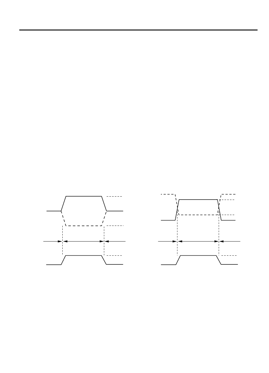
VOLTAGE TRANSFORMATION ON THE CAN-B BUS and CAN-C BUS

CAN_H

3.5 V

2.5 V

1.5 V

0

1

5 V

4 V

1 V

0 V

0

1

ZC5017690000

CAN_L

<CAN-C>

<CAN-B>

Voltage 
transformation 
in CAN_L

State: 

Logic value:

Recessive

Recessive

Dominant

Voltage 
transformation  
in CAN_H

Recessive

Recessive

Dominant

The voltage transformation (output signal) when the
data  frame  is  sent  to  the  CAN-C  bus  line  has  a
distinctive  CAN-C  profile.  The  transmitting  ECU
through the CAN_H and CAN_L bus lines sends 2.5
to 3.5 volts signals to the CAN_H side and 2.5 to 1.5
volts signals to the CAN_L side. The receiving ECU
reads the data from the CAN_H and CAN_L potential
difference. "Recessive" refers to the state where both
CAN_H and CAN_L are under the 2.5 volts state, and
"Dominant" refers to the state where CAN_H is under

CONTROLLER AREA NETWORK (CAN)

54D-5

SYSTEM OPERATION

the 3.5 volts state and CAN_L is under the 1.5 volts
state. On the other hand, the voltage transformation
(output  signal)  when  the  data  frame  is  sent  to  the
CAN-B bus line has a distinctive CAN-B profile. The
transmitting ECU through the CAN_H and CAN_L bus
lines sends 0 to 4 volts signals to the CAN_H side, and
1 to 5 volts signals to the CAN_L side. "Recessive" is
a state in which CAN_H is at 0 volt and CAN_L is at 5
volts, and "Dominant" is a state in which CAN_H is at

4  volts  and  CAN_L  is  at  1  volt.  By  transformation
mainly  to  2.5  volts,  even  in  cases  when  voltage  is
rendered 0 from faulty grounding or the like (causing
a problem of an approximate 0.5 volt increase on the
communications  line),  communication  can  be
continued

 uninterrupted.

 Employing

 dual

communications lines improves reliability to prevent
the presence of noise, compared to the conventional
communication method.

DATA FRAMES

ZC5017700000

SOF

EOF

ID 

region

CRC  

region

ACK  

region

Control  
region

Data region

Data frames

SOF (Start of Frame)

Indicates the start of the frame

ID (Identifier) region

Identifies the data content while specifying priority
rank in case of mediation

Control region

Specifies the frame type, data length, etc.

Data region

Values used for data control, etc.

Cyclic Redundancy Check (CRC) region

Region where to check for errors in sent data. The
transmitting  ECU  calculates  data  regions  by
applying  prescribed  operations  and  stores  the
results.  The  receiving  ECU  detects  erroneous

communication by comparing the CRC region with
the data region.

ACK (Acknowledge) region

Region where to conform the reception of sent data

EOF (End of Frame)

Indicates the end of the frame

ERROR DETECTION AND RECOVERY
CAN protocol secures its reliability of communication
by providing several error detection function such as
CRC shown in data frame, and the recovery function
(recovery is performed by resending, from abnormal
state  such  as  transmission  errors).  If  an  error  is
detected  but  it  is  not  resolved  even  after  recovery,
communication is stopped. This state is called "Bus
Off."

SELF-DIAGNOSIS

M25402000004USA0000010000

CAN  self-diagnosis  is  performed  by  each  ECU
connected to the CAN bus.

Diagnosis  codes  related  to  communication  are
named with the capital letter U, and are called "U-
codes."

A  summary  of  the  CAN  self-diagnosis  system  is
presented  below.  For  further  details  on  each
diagnostic trouble code stored by the ECUs.

TIME-OUT
Each ECU transmits data frames periodically. If the
data frame is not received within the specified period,
the  intended  receiving  ECU  transmits  a  diagnostic
trouble  code  indicating  communication  time-out  for
the ECU that failed to transmit.

54D-6

CONTROLLER AREA NETWORK (CAN)

SELF-DIAGNOSIS

BUS OFF
Related to a communication error that persists even
after  the  transmitting  ECU  attempts  recovery  for  a

specified  number  of  attempts  or  that  persists  for  a
specified  period  after  recovery.  Communication  is
stopped and this diagnostic code is issued.

CAN BUS DIAGNOSTICS

M25402000005USA0000010000

As ECUs are connected via CAN bus (including scan
tool),  always  diagnose  CAN  bus  to  confirm  its
normality when inspecting. Simply by performing scan
tool screen operations, the following inspections can
be  performed  automatically,  and  the  result  can  be
used to verify the CAN bus status.

Confirmation of diagnostic trouble code of ETACS-
ECU

Confirmation of communication of all ECUs

CONTROLLER AREA NETWORK (CAN)

54D-7

CAN BUS DIAGNOSTICS

MEMO

54D-8

CONTROLLER AREA NETWORK (CAN)


Content   ..  1338  1339  1340  1341   ..