Content .. 1325 1326 1327 1328 ..
Mitsubishi Outlander XL. Manual - part 1327
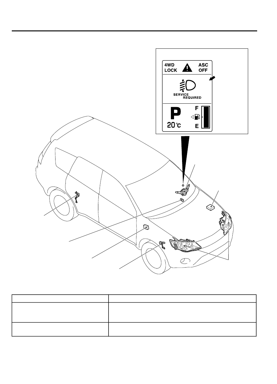
Construction diagram
ZC501813
Headlight
automatic
leveling
warning
display
Combination meter
(multi information display)
0000
Headlight assembly
(integrating motor)
Headlight automatic leveling ECU
Column switch
(lighting switch)
Height sensor (front)
Data link connector
Relay box in engine
compartment
(headlight relay : LO)
Height sensor (rear)
System component and function
Parts name
Functional description
Column switch (lighting switch)
When the lighting switch is set to the headlight position, the
headlight relay (LO) inside the engine compartment turns ON to
transmit the signal to the headlight automatic leveling ECU.
Height sensor (Front)
Detects the elongation/contraction of the front suspension and
transmits the signal to the headlight automatic leveling ECU.
54A-6
CHASSIS ELECTRICAL
LIGHTING