Content .. 1273 1274 1275 1276 ..
Mitsubishi Outlander XL. Manual - part 1275
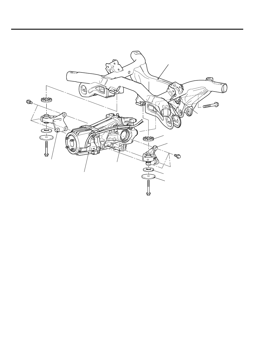
DIFFERENTIAL MOUNT
ZC5017870000
Rear suspension
crossmember
Upper stopper
Differential carrier
Electronic control coupling
Rear differential mount
front bracket (LH)
Rear differential
mount insulator
Lower stopper
Weight
Rear differential mount
front bracket (RH)
The front side of the differential carrier is installed to
the rear suspension crossmember via rear differential
mount front bracket (LH/RH). The rear side of the
differential carrier is installed to the rear suspension
crossmember via rear differential mount insulator. In
this way, the three-point support type differential
mount and the optimization of the layout reduces
vibration and noise.
ELECTRONIC CONTROL AWD
GENERAL INFORMATION
M22700000001USA0000010000
⦆
Electronic control AWD ensures performance,
lighter and smaller body, and better fuel economy.
⦆
The electronic control AWD controls the torque of
the electronic control coupling located between the
propeller shaft and rear differential. This strategy is
enabled by varying the torque distribution to the
front and rear wheels from the status closer to the
front wheel drive to the status closer to the direct
coupling AWD and realizes the optimal drive force
according to the various driving conditions.
AIMS OF DEVELOPMENT
Lightweight and simple construction of the electronic
control AWD achieves good fuel efficiency and
provides enjoyment of selecting the drive mode.
27-6
REAR AXLE
ELECTRONIC CONTROL AWD