Content .. 1221 1222 1223 1224 ..
Mitsubishi Outlander XL. Manual - part 1223
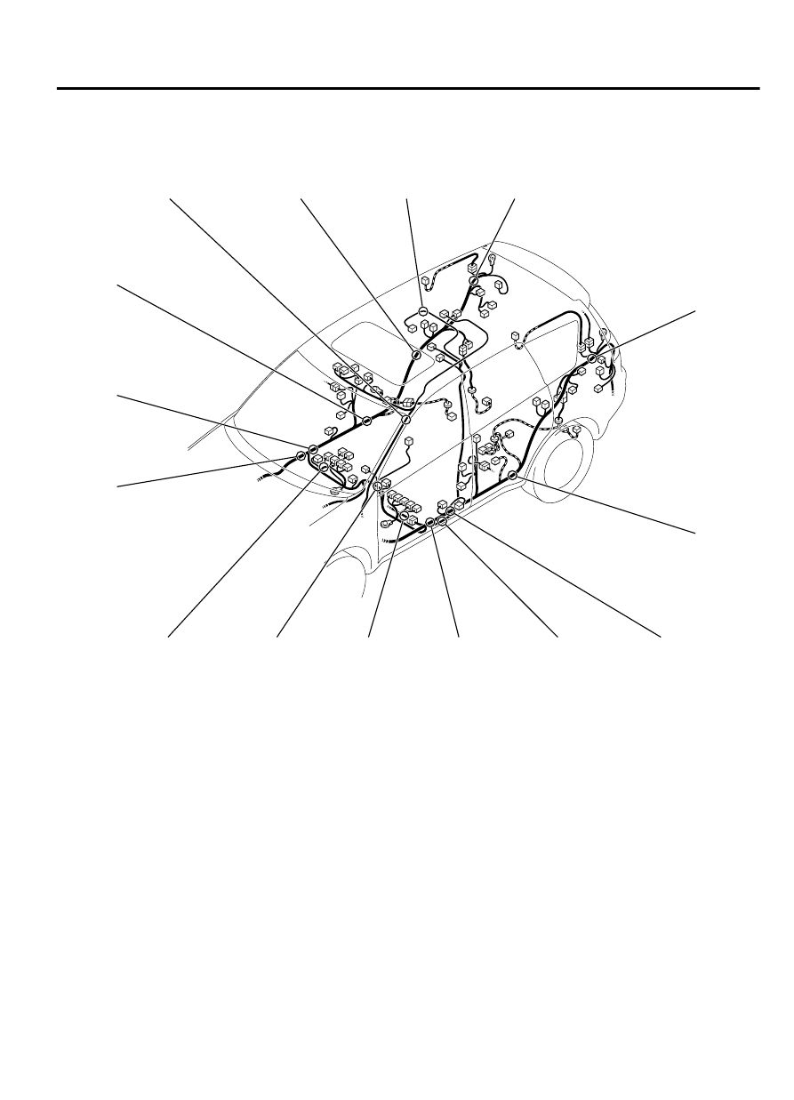
FLOOR AND ROOF
M18002000012USA0000010000
ZC6005960000
S076
S077
S078
S079
S080
S081 S084
S082 S085
S083
S086
S087
S089
S090
S091
S092 S095
S093 S096
S094
S097 S100
S098 S101
S099 S102
S103 S106
S104 S107
S105
S108
S109
S110
S111
S112
S113
S114
S116
SPLICE LOCATIONS
80B-7
FLOOR AND ROOF