Content .. 1167 1168 1169 1170 ..
Mitsubishi Outlander XL. Manual - part 1169
ZC5010410019
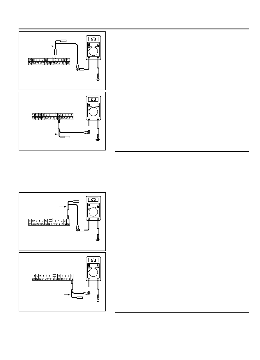
Harness side: C-103
Test
harness
(2)
Measure the resistance between joint connector (CAN1)
terminal 5 and body ground.
OK: 1 kiloohm or more
ZC5010410020
Harness side: C-103
Test
harness
(3)
Measure the resistance between joint connector (CAN1)
terminal 16 and body ground.
OK: 1 kiloohm or more
Q:Do all the resistances measure 1 kiloohm or more?
YES:
Go to Step 5.
NO:
Go to Step 50.
STEP 5. Check the wiring harness between joint connector
(CAN1) C-103 and SRS-ECU connector C-28 for a short to
ground. Measure the resistance at joint connector (CAN1)
C-103.
(1)
Disconnect joint connector (CAN1), and measure the
resistance at the wiring harness side of joint connector
(CAN1).
ZC5010410021
Harness side: C-103
Test
harness
(2)
Measure the resistance between joint connector (CAN1)
terminal 1 and body ground.
OK: 1 kiloohm or more
ZC5010410022
Harness side: C-103
Test
harness
(3)
Measure the resistance between joint connector (CAN1)
terminal 12 and body ground.
OK: 1 kiloohm or more
Q:Do all the resistances measure 1 kiloohm or more?
YES:
Go to Step 6.
NO:
Go to Step 51.
STEP 6. Check the wiring harness between joint connector
(CAN1) C-103 and occupant classification-ECU connector
CONTROLLER AREA NETWORK (CAN)
54D-159
DIAGNOSIS