Mitsubishi Outlander XL. Manual - part 1168


  Index      Mitsubishi     Mitsubishi Outlander XL - service repair manual 2007 year


Search            


Content   ..  1166  1167  1168  1169   ..


Mitsubishi Outlander XL. Manual - part 1168
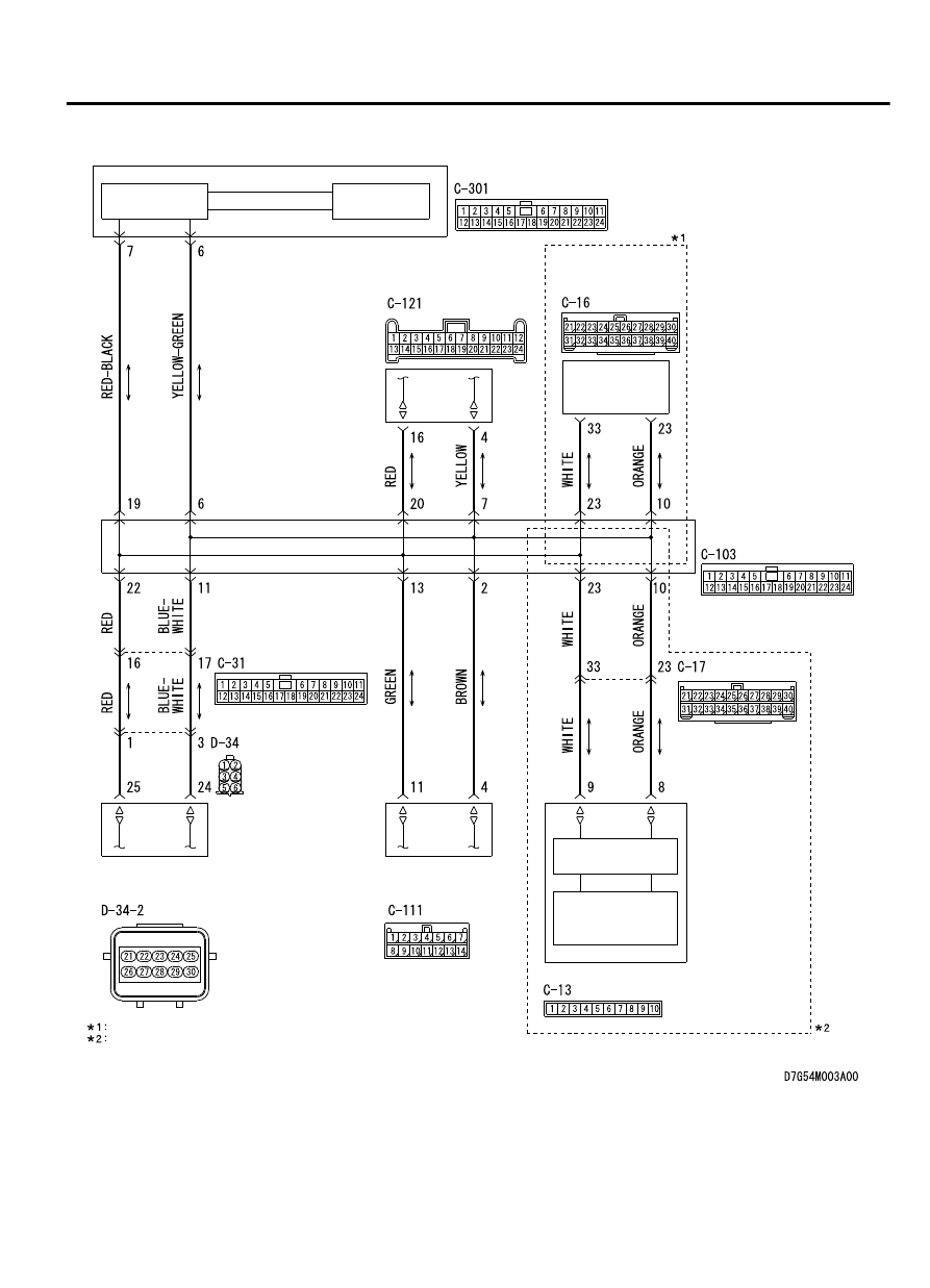


CAN Communication Circuit

ETACS-ECU

INTERFACE
CIRCUIT

INTERFACE
CIRCUIT

CAN DRIVE
CIRCUIT

HANDS FREE
MODULE

OCCUPANT 
CLASSIFICATION-
ECU

SATELLITE
RADIO 
TUNER

RADIO AND CD
PLAYER OR CD
CHANGER

NOTE

VEHICLES WITHOUT MITSUBISHI MULTI-COMMUNICATION SYSTEM (MMCS)
VEHICLES WITH MITSUBISHI MULTI-COMMUNICATION SYSTEM (MMCS)

CAN
TRANSCEIVER
CIRCUIT

CAN BOX UNIT

JOINT CONNECTOR
(CAN1)

CONTROLLER AREA NETWORK (CAN)

54D-155

DIAGNOSIS

ZC6008750013

Connectors: C-03, C-29, C-31, C-102, C-103

C-31

C-102

C-102

C-29

C-03

ZC6008760007

Connectors: C-13, C-16, C-17, C-28, C-109, 

C-111, C-121

C-111

C-109 (B)

C-13

C-16 or 
C-17

C-121

C-28 (Y)


ZC6008780000

Connector: C-301

ZC6008790000

Connector: D-34


FUNCTION
If a short to power supply or ground, open circuit or
line-to-line short is present at either CAN_H or CAN_L
side on the CAN-B lines, this diagnosis result will be
set.

TROUBLE JUDGEMENT CONDITIONS
When  CAN-B  lines  communication  is  normal,  and
diagnostic  trouble  code  U0019  is  set,  the  ETACS-
ECU determines that there is a failure.

TROUBLESHOOTING HINTS

Malfunction of the connector (short to power supply
or ground in connector or improperly connected)

Malfunction  of  the  wiring  harness  (short  to  power
supply or ground, open circuit or line-to-line short in
CAN bus lines)

Faulty  ECU(s)  (internal  short  to  power  supply  or
ground)

DIAGNOSIS

Required Special Tools:

MB991223: Harness Set

MB992006: Extra Fine Probe

STEP 1. Check the wiring harness between ETACS-ECU
connector C-301 and body ground for a short to ground.
Measure the resistance at ETACS-ECU connector C-301.

Disconnect the negative battery terminal. For details refer
to P.54D-8.

A digital multimeter should be used. For details refer to P.
54D-8.

54D-156

CONTROLLER AREA NETWORK (CAN)

DIAGNOSIS

The test wiring harness should be used. For details refer
to P.54D-8.

(1)

Disconnect ETACS-ECU connector C-301, and measure the
voltage at the wiring harness side of ETACS-ECU connector.

ZC5010410037

Harness side: C-301

Test 
harness

(2)

Measure  the  resistance  between  ETACS-ECU  connector
terminal 6 and body ground.

OK: 1 kiloohm or more

ZC5010410038

Harness side: C-301

Test 
harness

(3)

Measure  the  resistance  between  ETACS-ECU  connector
terminal 7 and body ground.

OK: 1 kiloohm or more

Q:Do all the resistances measure 1 kiloohm or more?

YES:

 Go to Step 2.

NO:

 Go to Step 13.

STEP 2. Check the wiring harness between joint connector
(CAN1) C-103 and combination meter connector C-03 for a
short to ground. Measure the resistance at joint connector
(CAN1) C-103.

(1)

Disconnect  joint  connector  (CAN1),  and  measure  the
resistance  at  the  wiring  harness  side  of  joint  connector
(CAN1).

ZC5010410015

Harness side: C-103

Test 
harness

(2)

Measure  the  resistance  between  joint  connector  (CAN1)
terminal 3 and body ground.

OK: 1 kiloohm or more

CONTROLLER AREA NETWORK (CAN)

54D-157

DIAGNOSIS

ZC5010410016

Harness side: C-103

Test 
harness

(3)

Measure  the  resistance  between  joint  connector  (CAN1)
terminal 14 and body ground.

OK: 1 kiloohm or more

Q:Do all the resistances measure 1 kiloohm or more?

YES(vehicles with KOS):

 Go to Step 3.

YES(vehicles with WCM):

 Go to Step 4.

NO(vehicles with KOS or WCM):

 Go to Step 48.

STEP 3. Check the wiring harness between joint connector
(CAN1) C-103 and KOS-ECU connector C-102 for a short to
ground. Measure the resistance at joint connector (CAN1)
C-103.

(1)

Disconnect  joint  connector  (CAN1),  and  measure  the
resistance  at  the  wiring  harness  side  of  joint  connector
(CAN1).

ZC5010410017

Harness side: C-103

Test harness

(2)

Measure  the  resistance  between  joint  connector  (CAN1)
terminal 8 and body ground.

OK: 1 kiloohm or more

ZC5010410018

Harness side: C-103

Test harness

(3)

Measure  the  resistance  between  joint  connector  (CAN1)
terminal 21 and body ground.

OK: 1 kiloohm or more

Q:Do all the resistances measure 1 kiloohm or more?

YES:

 Go to Step 5.

NO:

 Go to Step 49.

STEP 4. Check the wiring harness between joint connector
(CAN1) C-103 and WCM connector C-29 for a short to
ground. Measure the resistance at joint connector (CAN1)
C-103.

(1)

Disconnect  joint  connector  (CAN1),  and  measure  the
resistance  at  the  wiring  harness  side  of  joint  connector
(CAN1).

54D-158

CONTROLLER AREA NETWORK (CAN)

DIAGNOSIS


Content   ..  1166  1167  1168  1169   ..