Mitsubishi Outlander XL. Manual - part 1140


  Index      Mitsubishi     Mitsubishi Outlander XL - service repair manual 2007 year


Search            


Content   ..  1138  1139  1140  1141   ..


Mitsubishi Outlander XL. Manual - part 1140


ZC6008710000

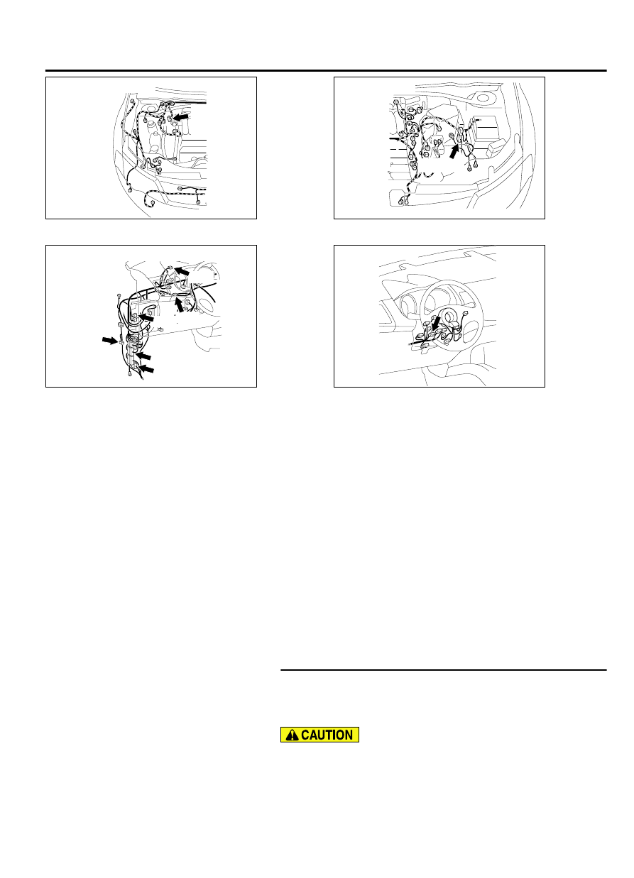
Connectors: A-01, A-02

A-01 (B) 
or 
A-02 (B)

ZC6008740000

Connector: B-11

B-11 (GR)


ZC6008750001

C-128

C-128

C-33

C-31

Connectors: C-01, C-04, C-31, C-33, C-38, 

C-04

C-01

C-38

ZC6008770000

Connector: C-209


FUNCTION
If a short to ground is present in the CAN-C lines, this
diagnosis result will be set.

TROUBLE JUDGEMENT CONDITIONS
If DTC U1120 is set, the ETACS-ECU determines that
there is a failure.

TROUBLESHOOTING HINTS

Malfunction of the connector (short to ground inside
connector)

Malfunction of the wiring harness (short to ground
in the CAN-C main or sub bus lines)

Malfunction of the ECU (ETACS-ECU, or ECUs on
CAN-C lines failed)

DIAGNOSIS

Required Special Tools:

MB991223: Harness Set

MB992006: Extra Fine Probe

MB991958: Scan Tool (M.U.T.-III Sub Assembly)

MB991824: Vehicle Communication Interface (V.C.I.)

MB991827: M.U.T.-III USB Cable

MB991910: M.U.T.-III Main Harness A

STEP 1. Check the wiring harness between joint connector
(CAN2) C-04 and steering wheel sensor connector C-209 for
a short to ground. Measure the resistance at joint connector
(CAN2) C-04.

Disconnect the negative battery terminal. For details refer
to P.54D-8.

CONTROLLER AREA NETWORK (CAN)

54D-43

DIAGNOSIS

A digital multimeter should be used. For details refer to P.
54D-8.

The test wiring harness should be used. For details refer
to P.54D-8.

(1)

Disconnect  joint  connector  (CAN2),  and  measure  the
resistance  at  the  wiring  harness  side  of  joint  connector
(CAN2).

ZC5010410002

Harness side: C-04

Test 
harness

(2)

Measure  the  resistance  between  joint  connector  (CAN2)
terminal 4 and body ground.

OK: 1 kiloohm or more

ZC5010410003

Harness side: C-04

Test 
harness

(3)

Measure  the  resistance  between  joint  connector  (CAN2)
terminal 15 and body ground.

OK: 1 kiloohm or more

Q:Do all the resistances measure 1 kiloohm or more?

YES:

 Go to Step 2.

NO:

 Go to Step 7.

STEP 2. Check the wiring harness between joint connector
(CAN2) C-04 and AWD-ECU connector C-128 for a short to
ground. Measure the resistance at joint connector (CAN2)
C-04.

(1)

Disconnect  joint  connector  (CAN2),  and  measure  the
resistance  at  the  wiring  harness  side  of  joint  connector
(CAN2).

ZC5010410004

Harness side: C-04

Test 
harness

(2)

Measure  the  resistance  between  joint  connector  (CAN2)
terminal 5 and body ground.

OK: 1 kiloohm or more

54D-44

CONTROLLER AREA NETWORK (CAN)

DIAGNOSIS

ZC5010410005

Harness side: C-04

Test 
harness

(3)

Measure  the  resistance  between  joint  connector  (CAN2)
terminal 16 and body ground.

OK: 1 kiloohm or more

Q:Do all the resistances measure 1 kiloohm or more?

YES:

 Go to Step 3.

NO:

 Go to Step 8.

STEP 3. Check the wiring harness between joint connector
(CAN2) C-04 and ETACS-ECU connector C-301 for a short
to ground. Measure the resistance at joint connector (CAN2)
C-04.

(1)

Disconnect  joint  connector  (CAN2),  and  measure  the
resistance  at  the  wiring  harness  side  of  joint  connector
(CAN2).

ZC5010410006

Harness side: C-04

Test harness

(2)

Measure  the  resistance  between  joint  connector  (CAN2)
terminal 6 and body ground.

OK: 1 kiloohm or more

ZC5010410007

Harness side: C-04

Test 
harness

(3)

Measure  the  resistance  between  joint  connector  (CAN2)
terminal 19 and body ground.

OK: 1 kiloohm or more

Q:Do all the resistances measure 1 kiloohm or more?

YES:

 Go to Step 4.

NO:

 Go to Step 9.

STEP 4. Check the wiring harness between joint connector
(CAN3) C-01 and ECM connector B-11 for a short to ground.
Measure the resistance at joint connector (CAN3) C-01.

(1)

Disconnect  joint  connector  (CAN3),  and  measure  the
resistance  at  the  wiring  harness  side  of  joint  connector
(CAN3).

CONTROLLER AREA NETWORK (CAN)

54D-45

DIAGNOSIS

ZC5010410008

Harness side: C-01

Test 
harness

(2)

Measure  the  resistance  between  joint  connector  (CAN3)
terminal 4 and body ground.

OK: 1 kiloohm or more

ZC5010410009

Harness side: C-01

Test 
harness

(3)

Measure  the  resistance  between  joint  connector  (CAN3)
terminal 15 and body ground.

OK: 1 kiloohm or more

Q:Do all the resistances measure 1 kiloohm or more?

YES:

 Go to Step 5.

NO:

 Go to Step 10.

STEP 5. Check the wiring harness between joint connector
(CAN3) C-01 and ABS-ECU connector A-01 <vehicles
without ASC> or ASC-ECU connector A-02 <vehicles with
ASC> for a short to ground. Measure the resistance at joint
connector (CAN3) C-01.

(1)

Disconnect  joint  connector  (CAN3),  and  measure  the
resistance  at  the  wiring  harness  side  of  joint  connector
(CAN3).

ZC5010410010

Harness side: C-01

Test harness

(2)

Measure  the  resistance  between  joint  connector  (CAN3)
terminal 6 and body ground.

OK: 1 kiloohm or more

ZC5010410011

Harness side: C-01

Test 
harness

(3)

Measure  the  resistance  between  joint  connector  (CAN3)
terminal 19 and body ground.

OK: 1 kiloohm or more

Q:Do all the resistances measure 1 kiloohm or more?

YES:

 Go to Step 6.

NO:

 Go to Step 11.

54D-46

CONTROLLER AREA NETWORK (CAN)

DIAGNOSIS


Content   ..  1138  1139  1140  1141   ..