Mitsubishi Outlander XL. Manual - part 1139


  Index      Mitsubishi     Mitsubishi Outlander XL - service repair manual 2007 year


Search            


Content   ..  1137  1138  1139  1140   ..


Mitsubishi Outlander XL. Manual - part 1139


ZC5018690001

: Red section on scree n

M. U . T .

J/C (3)

J/C (2)

SAS

4WD

K OS/WC

M

SRS

OCM

A/C

A UDI O

MMCS

Sat Radio

HFM

METER

ABS/ASC

A T

ENGINE

E T A C S

J/C (1)

(4)

Diagnose  CAN  bus  lines,  and  check  if  the  scan  tool
MB991958 screen is as shown in the figure.

OK:  The  display  of  the  scan  tool  MB991958  is  as
shown in the figure.

Q:Does  scan  tool  MB991958  screen  correspond  to  the

illustration?

YES:

 Repair the wiring harness between ABS-ECU connector

A-01 <vehicles without ASC> or ASC-ECU connector A-02
<vehicles with ASC> and joint connector (CAN3) C-01.

NO:

 Check ABS-ECU connector A-01 <vehicles without ASC>

or ASC-ECU connector A-02 <vehicles with ASC>, and repair
if necessary. If the ABS-ECU <vehicles without ASC> or
ASC-ECU <vehicles with ASC> connector is in good
condition, replace the ABS-ECU <vehicles without ASC> or
ASC-ECU <vehicles with ASC>.

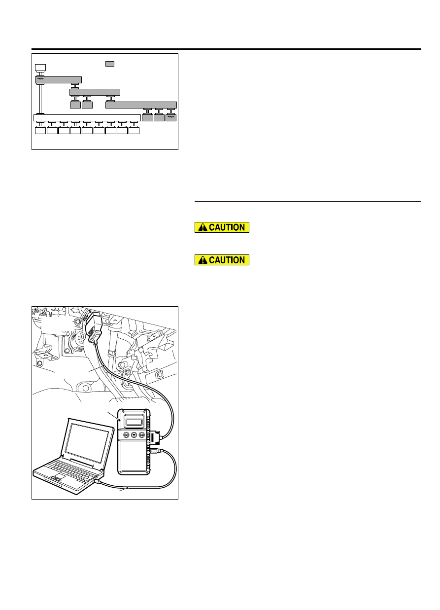
STEP 12. Using scan tool MB991958, diagnose the CAN bus
line. (checking the TCM for internal short)

Strictly  observe  the  specified  wiring  harness  repair
procedure. For details refer to P.54D-8.

To prevent damage to scan tool MB991958, always turn the
ignition  switch  to  the  "LOCK"  (OFF)  position  before
connecting or disconnecting scan tool MB991958.

(1)

Disconnect TCM connector C-38.

ZC501967

AC404789

ZC5019680000

MB991824

MB991827

MB991910

Data link

connector

(2)

Connect scan tool MB991958 to the data link connector.

(3)

Turn the ignition switch to the "ON" position.

CONTROLLER AREA NETWORK (CAN)

54D-39

DIAGNOSIS

ZC5018690001

: Red section on scree n

M. U . T .

J/C (3)

J/C (2)

SAS

4WD

K OS/WC

M

SRS

OCM

A/C

A UDI O

MMCS

Sat Radio

HFM

METER

ABS/ASC

A T

ENGINE

E T A C S

J/C (1)

(4)

Diagnose  CAN  bus  lines,  and  check  if  the  scan  tool
MB991958 screen is as shown in the figure.

OK:  The  display  of  the  scan  tool  MB991958  is  as
shown in the figure.

Q:Does  scan  tool  MB991958  screen  correspond  to  the

illustration?

YES:

 Repair the wiring harness between TCM connector C-38

and joint connector (CAN3) C-01.

NO:

 Check TCM connector C-38, and repair if necessary.

If the TCM connector is in good condition, replace the
TCM.

STEP 13. Check the wiring harness between joint connector
(CAN2) C-04 and ETACS-ECU connector C-301 for line-to-
line short. Measure the resistance at joint connector (CAN2)
C-04.

(1)

Disconnect  joint  connector  (CAN2)  and  ETACS-ECU
connector, and check that there is continuity at the harness
side of joint connector (CAN2).

ZC5010390006

Test 
harness

Test 
harness

Harness side: C-04

(2)

Check  that  there  is  continuity  between  joint  connector
(CAN2) terminals 7 and 20.

OK: No continuity

Q:Is the check result normal?

YES:

 Go to Step 14.

NO:

 Repair the wiring harness between joint connector

(CAN2) C-04 and ETACS-ECU connector C-301.

STEP 14. Using scan tool MB991958, diagnose the CAN bus
line.

ZC501967

AC404789

ZC5019680000

MB991824

MB991827

MB991910

Data link

connector

To prevent damage to scan tool MB991958, always turn the
ignition  switch  to  the  "LOCK"  (OFF)  position  before
connecting or disconnecting scan tool MB991958.

(1)

Connect scan tool MB991958 to the data link connector.

(2)

Turn the ignition switch to the "ON" position.

54D-40

CONTROLLER AREA NETWORK (CAN)

DIAGNOSIS

ZC5018690000

: Red section on scree n

M. U . T .

J/C (3)

J/C (2)

SAS

4WD

K OS/WC

M

SRS

OCM

A/C

A UDI O

MMCS

Sat Radio

HFM

METER

ABS/ASC

A T

ENGINE

E T A C S

J/C (1)

(3)

Diagnose CAN bus lines, and check if the scan tool screen
is as shown in the illustration.

Q:Does the scan tool screen correspond to the illustration?

YES:

 The trouble can be an intermittent malfunction

(Refer to GROUP 00, How to use Troubleshooting/inspection
Service Points - How to Cope with Intermittent
Malfunction P.00-15).

NO:

 Replace the ETACS-ECU.

DIAGNOSTIC ITEM 4: Diagnose shorts in the ground to CAN-C bus line.

M15408300009USA0000010000

When servicing a CAN bus line, ground yourself
by touching a metal object such as an unpainted

water  pipe.  If  you  fail  to  do  so,  a  component
connected to the CAN bus line may be damaged.

CONTROLLER AREA NETWORK (CAN)

54D-41

DIAGNOSIS

CAN Communication Circuit

ETACS-ECU

INTERFACE
CIRCUIT

CAN DRIVE
CIRCUIT

STEERING WHEEL
SENSOR

AWD-ECU

JOINT CONNECTOR
(CAN2)

JOINT CONNECTOR
(CAN3)

TRANSMISSION
CONTROL
MODULE

ASC-ECU

ABS-ECU

ENGINE
CONTROL
MODULE

NOTE

VEHICLES WITHOUT ASC
VEHICLES WITH ASC

54D-42

CONTROLLER AREA NETWORK (CAN)

DIAGNOSIS


Content   ..  1137  1138  1139  1140   ..