Mitsubishi Outlander XL. Manual - part 1117


  Index      Mitsubishi     Mitsubishi Outlander XL - service repair manual 2007 year


Search            


Content   ..  1115  1116  1117  1118   ..


Mitsubishi Outlander XL. Manual - part 1117


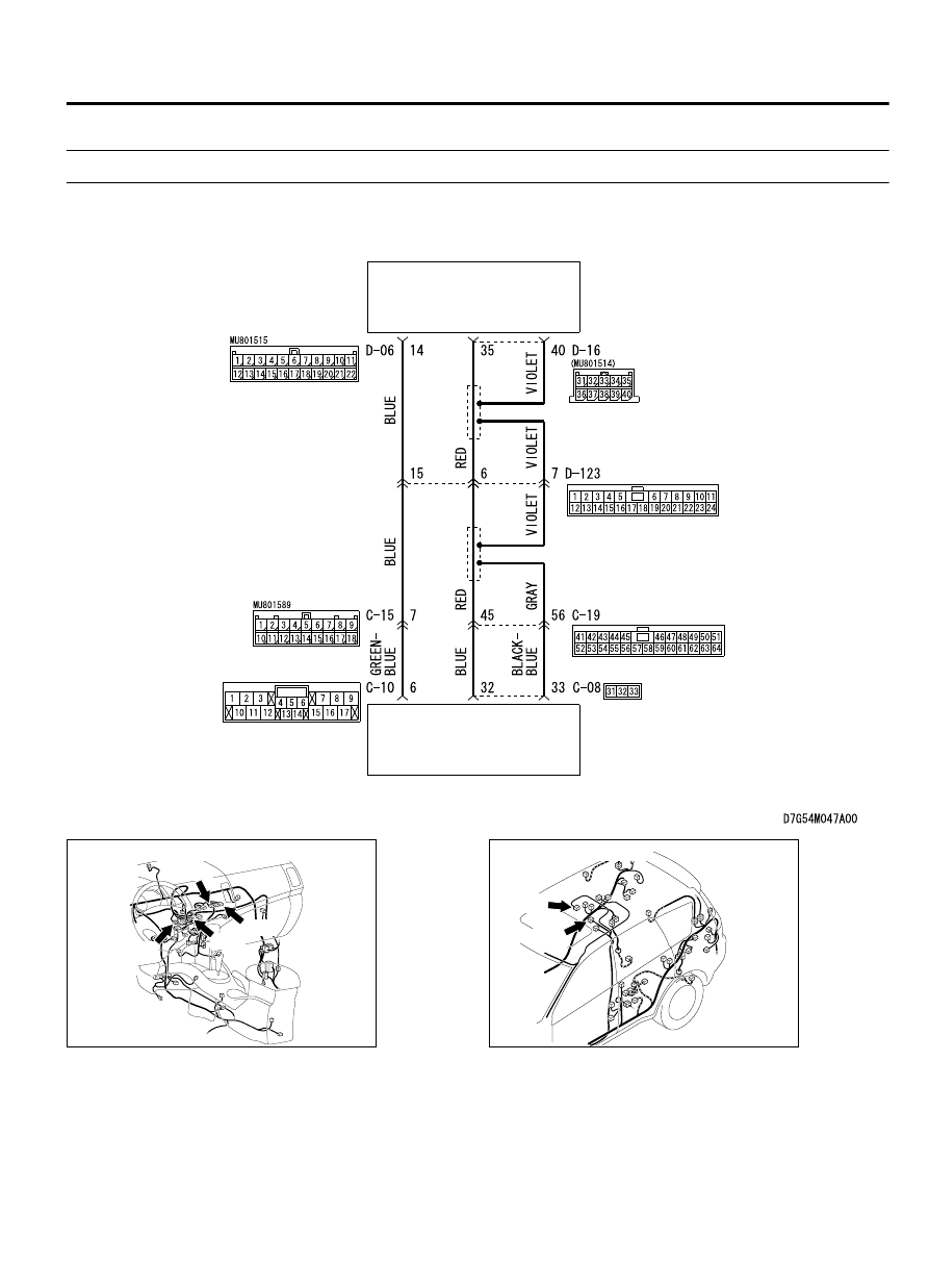
Inspection Procedure 5: The rear display not displays the navigation system picture.

M15410800365USA0000010000

Audio Communication Circuit

REAR DISPLAY UNIT

AUDIO VISUAL
NAVIGATION UNIT

ZC6008760010

Connectors: C-08, C-10, C-15, C-19

C-08

C-10

C-15

C-19

ZC6008800002

Connectors: D-06, D-16

D-06 (L)

D-16


AUDIO AND NAVIGATION SYSTEM

54B-149

DIAGNOSIS

ZC6008790003

Connector: D-123

DIAGNOSIS

Required Special Tools:

MB991223: Harness Set

MB992006: Extra Fine Probe

MB991958: Scan Tool (M.U.T.-III Sub Assembly)

MB991824: Vehicle Communication Interface (V.C.I.)

MB991827: M.U.T.-III USB Cable

MB991910: M.U.T.-III Main Harness A

STEP 1. Check the MMCS navigation screen.
Check  whether  the  MMCS  navigation  screen  is  displayed
normally.

Q:Is the check result normal?

YES:

 Go to Step 2.

NO:

 Diagnose the MMCS. Refer to P.54B-74.

STEP 2. Check the communication and wire connection in
the MMCS service mode.
Perform  "Network/Connect  Line  Check"  in  the  MMCS  service
mode to check that the communication and wire connection with
the rear display unit*are OK. Refer to P.54B-64.

NOTE: 

*: Is displayed as "Rear Seat Display" in the service

mode.

Q:Is the check result normal?

YES:

 Go to Step 3.

NO:

 Go to Step 5.

STEP 3. Check rear display unit connector D-16 and audio
visual navigation unit connector C-08 for loose, corroded or
damaged terminals, or terminals pushed back in the
connector.

Q:Is  rear  display  unit  connector  D-16  and  audio  visual

navigation unit connector C-08 in good condition?

YES:

 Go to Step 4.

NO:

 Repair or replace the damaged component(s). Refer to

GROUP 00E, Harness Connector Inspection P.00E-2.

54B-150

AUDIO AND NAVIGATION SYSTEM

DIAGNOSIS

STEP 4. Check the wiring harness between rear display unit
connector D-16 (terminal 35, 40) and audio visual navigation
unit connector C-08 (terminal 32, 33).

Check the communication lines for open circuit.

NOTE: 

Also check intermediate connectors C-19 and D-123 for

loose, corroded, or damaged terminals, or terminals pushed
back in the connector. If intermediate connector C-19 or
D-123 is damaged, repair or replace the connector as
described in GROUP 00E, Harness Connector Inspection P.
00E-2.

Q:Is the wiring harness between rear display unit connector

D-16  (terminal  35,  40)  and  audio  visual  navigation  unit

connector C-08 (terminal 32, 33) in good condition?

YES:

 Go to Step 5.

NO:

 The wiring harness may be damaged or the connector

(s) may have loose, corroded or damaged terminals, or
terminals pushed back in the connector. Repair the wiring
harness as necessary.

STEP 5. Check rear display unit connector D-06 and audio
visual navigation unit connector C-10 for loose, corroded or
damaged terminals, or terminals pushed back in the
connector.

Q:Is  rear  display  unit  connector  D-06  and  audio  visual

navigation unit connector C-10 in good condition?

YES:

 Go to Step 6.

NO:

 Repair or replace the damaged component(s). Refer to

GROUP 00E, Harness Connector Inspection P.00E-2.

STEP 6. Check the wiring harness between rear display unit
connector D-06 (terminal 14) and audio visual navigation
unit connector C-10 (terminal 6).

Check the communication lines for open circuit.

NOTE: 

Also check intermediate connectors C-15 and D-123 for

loose, corroded, or damaged terminals, or terminals pushed
back in the connector. If intermediate connector C-15 or
D-123 is damaged, repair or replace the connector as
described in GROUP 00E, Harness Connector Inspection P.
00E-2.

Q:Is the wiring harness between rear display unit connector

D-06  (terminal  14)  and  audio  visual  navigation  unit

connector C-10 (terminal 6) in good condition?

YES:

 Go to Step 7.

NO:

 The wiring harness may be damaged or the connector

(s) may have loose, corroded or damaged terminals, or
terminals pushed back in the connector. Repair the wiring
harness as necessary.

STEP 7. Substitute a known good rear display unit, and
check the trouble symptom.
Check whether image sent from the MMCS is displayed on the
rear display unit normally.

AUDIO AND NAVIGATION SYSTEM

54B-151

DIAGNOSIS

Q:Is the check result normal?

YES:

 Replace the rear display unit.

NO:

 Replace the audio visual navigation unit.

Inspection Procedure 6: The picture and sound of external input are not played.

M15410800242USA0000010000

Audio and Video Adapter Communication Circuit

REAR DISPLAY UNIT

AUDIO AND 
VIDEO ADAPTER

54B-152

AUDIO AND NAVIGATION SYSTEM

DIAGNOSIS


Content   ..  1115  1116  1117  1118   ..