Content .. 1114 1115 1116 1117 ..
Mitsubishi Outlander XL. Manual - part 1116
ZC5010400042
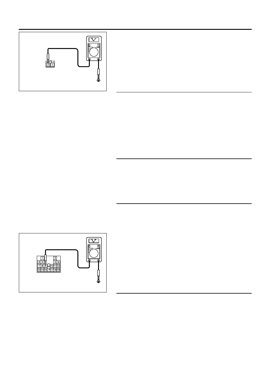
Harness side: C-309
(3)
Measure the voltage between terminal 2 and ground.
OK: The voltage should measure approximately 12
volts (battery positive voltage).
Q:Is the measured voltage approximately 12 volts (battery
positive voltage)?
YES:
Go to Step 8.
NO:
Go to Step 7.
STEP 7. Check the wiring harness between ETACS-ECU
connector C-309 (terminal 2) and fusible link No.37.
⦆
Check the power supply line for open circuit and short circuit.
Q:Is the wiring harness between ETACS-ECU connector
C-309 (terminal 2) and fusible link No.37 in good
condition?
YES:
Go to Step 8.
NO:
The wiring harness may be damaged or the connector
(s) may have loose, corroded or damaged terminals, or
terminals pushed back in the connector. Repair the wiring
harness as necessary.
STEP 8. Check ETACS-ECU connector C-315 for loose,
corroded or damaged terminals, or terminals pushed back
in the connector.
Q:Is ETACS-ECU connector C-315 in good condition?
YES:
Go to Step 9.
NO:
Repair or replace the damaged component(s). Refer to
GROUP 00E, Harness Connector Inspection P.00E-2.
STEP 9. Check the power supply circuit to the ETACS-ECU.
Measure the voltage at ETACS-ECU connector C-315.
(1)
Disconnect the connector, and measure at the ETACS-ECU
side connector.
(2)
Turn the ignition switch to the "ACC" position.
ZC5010400048
Component side: C-315
(3)
Measure voltage between terminal 9 and ground.
OK: Battery voltage
Q:Is the measured voltage battery voltage?
YES:
Go to Step 10.
NO:
Replace the ETACS-ECU.
STEP 10. Check the wiring harness between ETACS-ECU
connector C-315 (terminal 9) and rear display unit
connector D-06 (terminal 4).
NOTE:
Also check intermediate connector D-123 for loose,
corroded, or damaged terminals, or terminals pushed back in
the connector. If intermediate connector D-123 is damaged,
AUDIO AND NAVIGATION SYSTEM
54B-145
DIAGNOSIS