Content .. 1112 1113 1114 1115 ..
Mitsubishi Outlander XL. Manual - part 1114
DIAGNOSIS
Required Special Tools:
⦆
MB991223: Harness Set
⦆
MB992006: Extra Fine Probe
⦆
MB991958: Scan Tool (M.U.T.-III Sub Assembly)
⦆
MB991824: Vehicle Communication Interface (V.C.I.)
⦆
MB991827: M.U.T.-III USB Cable
⦆
MB991910: M.U.T.-III Main Harness A
STEP1. Check whether AM or FM broadcast frequency is
received.
Check whether AM or FM broadcast frequency is received.
Q:Is AM or FM broadcast frequency received?
YES:
Go to Step 2.
NO:
Diagnose the radio <vehicles with radio and CD
changer> or the audio visual navigation unit <vehicles
with MMCS>. Refer to P.54B-18<vehicles with radio and CD
changer> or P.54B-74<vehicles with MMCS>.
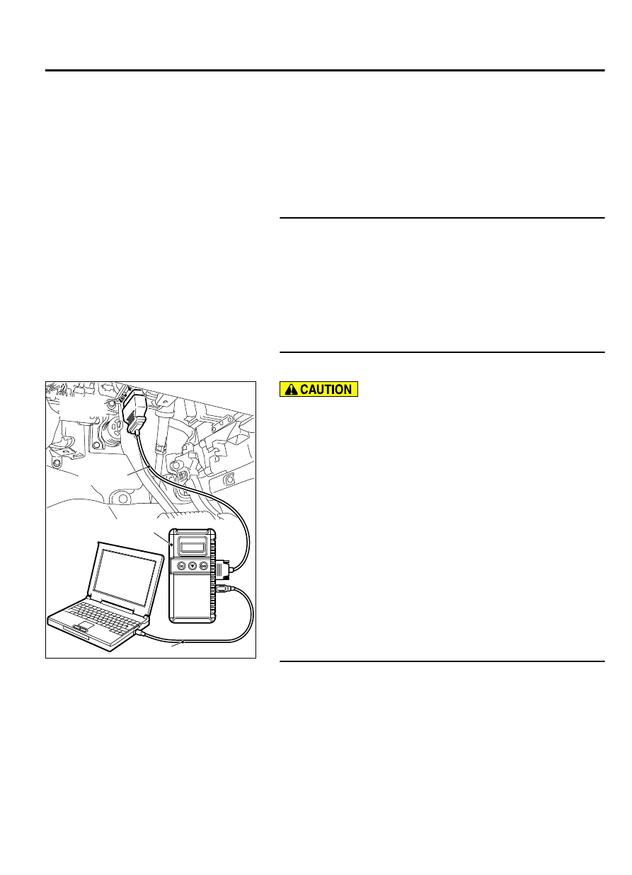
STEP 2. Using scan tool MB991958, diagnose the CAN bus
line.
ZC501967
AC404789
ZC5019680000
MB991824
MB991827
MB991910
Data link
connector
To prevent damage to scan tool MB991958, always turn the
ignition switch to the "LOCK" (OFF) position before
connecting or disconnecting scan tool MB991958.
(1)
Connect scan tool MB991958. Refer to GROUP 54Ad,
ETACS, Diagnosis, "How to connect the Scan Tool (M.U.T.-
III) P.54Ad-5."
(2)
Turn the ignition switch to the "ON" position.
(3)
Diagnose the CAN bus line.
(4)
Turn the ignition switch to the "LOCK" (OFF) position.
Q:Is the CAN bus line found to be normal?
YES<vehicles with radio and CD changer>:
Go to Step 3.
YES<vehicles with MMCS>:
Go to Step 6.
NO<vehicles with radio and CD changer or MMCS>:
Repair the CAN bus line. (Refer to GROUP 54D,
Diagnosis P.54D-17).
STEP 3. Check satellite radio tuner connector C-111 and
radio and CD changer connector C-14 for loose, corroded
or damaged terminals, or terminals pushed back in the
connector.
Q:Is satellite radio tuner connector C-111 or radio and CD
changer connector C-14 in good condition?
YES:
Go to Step 4.
AUDIO AND NAVIGATION SYSTEM
54B-137
DIAGNOSIS