Mitsubishi Outlander XL. Manual - part 1112


  Index      Mitsubishi     Mitsubishi Outlander XL - service repair manual 2007 year


Search            


Content   ..  1110  1111  1112  1113   ..


Mitsubishi Outlander XL. Manual - part 1112


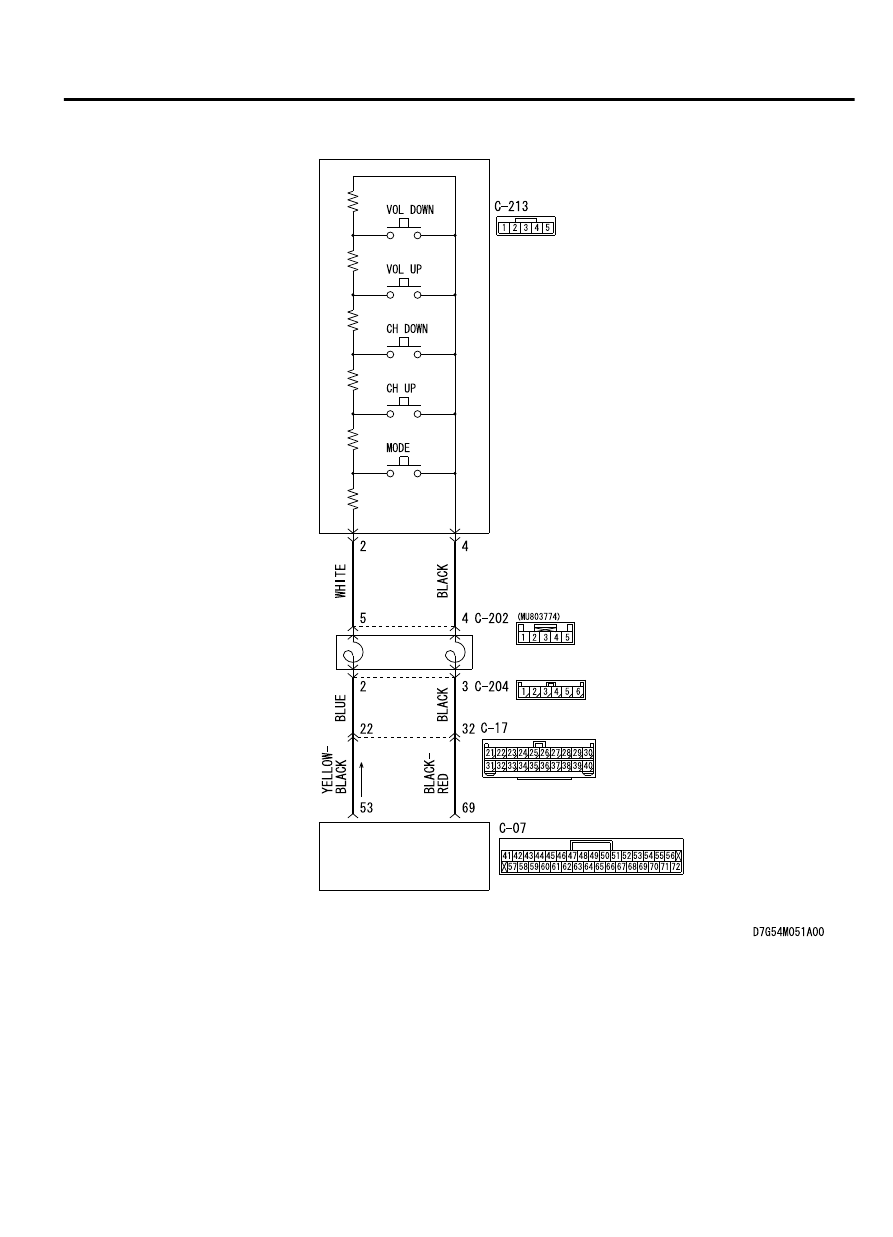
Steering Audio Switch Circuit

AUDIO VISUAL 
NAVIGATION UNIT

CLOCK 
SPRING

STEERING 
AUDIO 
SWITCH

AUDIO AND NAVIGATION SYSTEM

54B-129

DIAGNOSIS

ZC6008760019

Connectors: C-07, C-17

C-07

C-17

ZC6008770003

Connectors: C-202, C-204, C-213

C-213 (R)

C-202

C-204


TECHNICAL DESCRIPTION (COMMENT)
The power supply circuit to the steering remote control
switch, the steering remote control switch, the audio
visual  navigation  unit,  or  the  clock  spring  may  be
defective.

TROUBLESHOOTING HINTS

Malfunction of steering remote control switch

Malfunctions of audio visual navigation unit

Malfunction of the clock spring

Damaged harness wires and connectors

DIAGNOSIS

Required Special Tools:

MB991223: Harness Set

MB992006: Extra Fine Probe

MB991958: Scan Tool (M.U.T.-III Sub Assembly)

MB991824: Vehicle Communication Interface (V.C.I.)

MB991827: M.U.T.-III USB Cable

MB991910: M.U.T.-III Main Harness A

STEP 1. Using scan tool MB991958, check data list.
Check whether the service data below are normal.

(1)

Turn the ignition switch to "ON" position.

(2)

Operate each switch of the steering remote control. Check
whether the normal conditions listed below are displayed.

Item No. Item name

Normal
condition

Item 1

RADIO remoto SW (SEEK-)

ON

Item 2

RADIO remoto SW (SEEK+)

ON

Item 3

RADIO remoto SW (MODE)

ON

Item 4

RADIO remoto SW (VOL-)

ON

Item 5

RADIO remoto SW (VOL+)

ON

OK: Normal condition is displayed.

Q:Is the check result normal?

YES:

 Replace the audio visual navigation unit.

NO:

 Go to Step 2.

54B-130

AUDIO AND NAVIGATION SYSTEM

DIAGNOSIS

STEP 2. Check the remote controlled radio switch.

ZC6019360000

“VOL up” switch

“CH up” 
switch

“CH down” 
switch

“VOL down” 
switch

“Mode” switch

ZC6016200000

Remove  the  remote  controlled  radio  switch.  Then  check
continuity between the switch terminals.

Switch Position Tester

Connection

Measurement Value

No push

2 - 3

Approximately 3.1 kΩ

2 - 4

Approximately 71 kΩ

Mode

Approximately 270 Ω

CH up

Approximately 740 Ω

CH down

Approximately 1.3 kΩ

VOL up

Approximately 2.1 kΩ

VOL down

Approximately 3.1 kΩ

Q:Is the remote controlled radio switch in good condition?

YES:

 Go to Step 3.

NO:

 Replace the remote controlled radio switch.

STEP 3. Check clock spring connector C-202 and C-204 for
loose, corroded or damaged terminals, or terminals pushed
back in the connector.

Q:Are  clock  spring  connector  C-202  and  C-204  in  good

condition?

YES:

 Go to Step 4.

NO:

 Repair or replace the damaged component(s). Refer to

GROUP 00E, Harness Connector Inspection P.00E-2. The
steering remote control switch should work normally.

STEP 4. Check the clock spring.
Check whether the clock spring is in good condition. Refer to
GROUP 52B, Air bag module and clock spring P.52B-336.

Q:Is the check result normal?

YES:

 Go to Step 5.

NO:

 Replace the clock spring.

STEP 5. Check audio visual navigation unit connector C-07
for loose, corroded or damaged terminals, or terminals
pushed back in the connector.

Q:Is  audio  visual  navigation  unit  connector  C-07  in  good

condition?

YES:

 Go to Step 6.

NO:

 Repair or replace the damaged component(s). Refer to

GROUP 00E, Harness Connector Inspection P.00E-2. The
steering remote control switch should work normally.

AUDIO AND NAVIGATION SYSTEM

54B-131

DIAGNOSIS

STEP 6. Check the wiring harness between audio visual
navigation unit connector C-07 (terminal 53, 69) and clock
spring connector C-204 (terminal 2, 3).

NOTE: 

Also check intermediate connector C-17 for loose,

corroded, or damaged terminals, or terminals pushed back in
the connector. If intermediate connector C-17 is damaged,
repair or replace the connector as described in GROUP 00E,
Harness Connector Inspection P.00E-2.

Check the communication lines for open or short circuit.

Q:Is  the  wiring  harness  between  audio  visual  navigation

unit  connector  C-07  (terminal  53,  69)  and  clock  spring

connector C-204 (terminal 2, 3) in good condition?

YES:

 Go to Step 7.

NO:

 The wiring harness may be damaged or the connector

(s) may have loose, corroded or damaged terminals, or
terminals pushed back in the connector. Repair the wiring
harness as necessary.

STEP 7. Check steering remote control switch connector
C-213 for loose, corroded or damaged terminals, or
terminals pushed back in the connector.

Q:Is  steering  remote  control  switch  connector  C-213  in

good condition?

YES:

 Go to Step 8.

NO:

 Repair or replace the damaged component(s). Refer to

GROUP 00E, Harness Connector Inspection P.00E-2. The
steering remote control switch should work normally.

STEP 8. Check the wiring harness between steering remote
control switch connector C-213 (terminal 2, 4) and clock
spring connector C-202 (terminal 5, 4).

Check the communication lines for open or short circuit.

Q:Is  the  wiring  harness  between  steering  remote  control

switch connector C-213 (terminal 2, 4) and clock spring

connector C-202 (terminal 5, 4) in good condition?

YES:


Go to Step 9.

NO:

 The wiring harness may be damaged or the connector

(s) may have loose, corroded or damaged terminals, or
terminals pushed back in the connector. Repair the wiring
harness as necessary.

STEP 9. Retest the system
Check whether you can operate the audio visual navigation unit
by using the steering remote control.

Q:Is the check result normal?

YES:

 The trouble can be an intermittent malfunction

(Refer to GROUP 00, How to use Troubleshooting/inspection
Service Points, How to Cope with Intermittent
Malfunction P.00-15).

NO:

 Replace the audio visual navigation unit.

54B-132

AUDIO AND NAVIGATION SYSTEM

DIAGNOSIS


Content   ..  1110  1111  1112  1113   ..