Mitsubishi Outlander XL. Manual - part 1113


  Index      Mitsubishi     Mitsubishi Outlander XL - service repair manual 2007 year


Search            


Content   ..  1111  1112  1113  1114   ..


Mitsubishi Outlander XL. Manual - part 1113


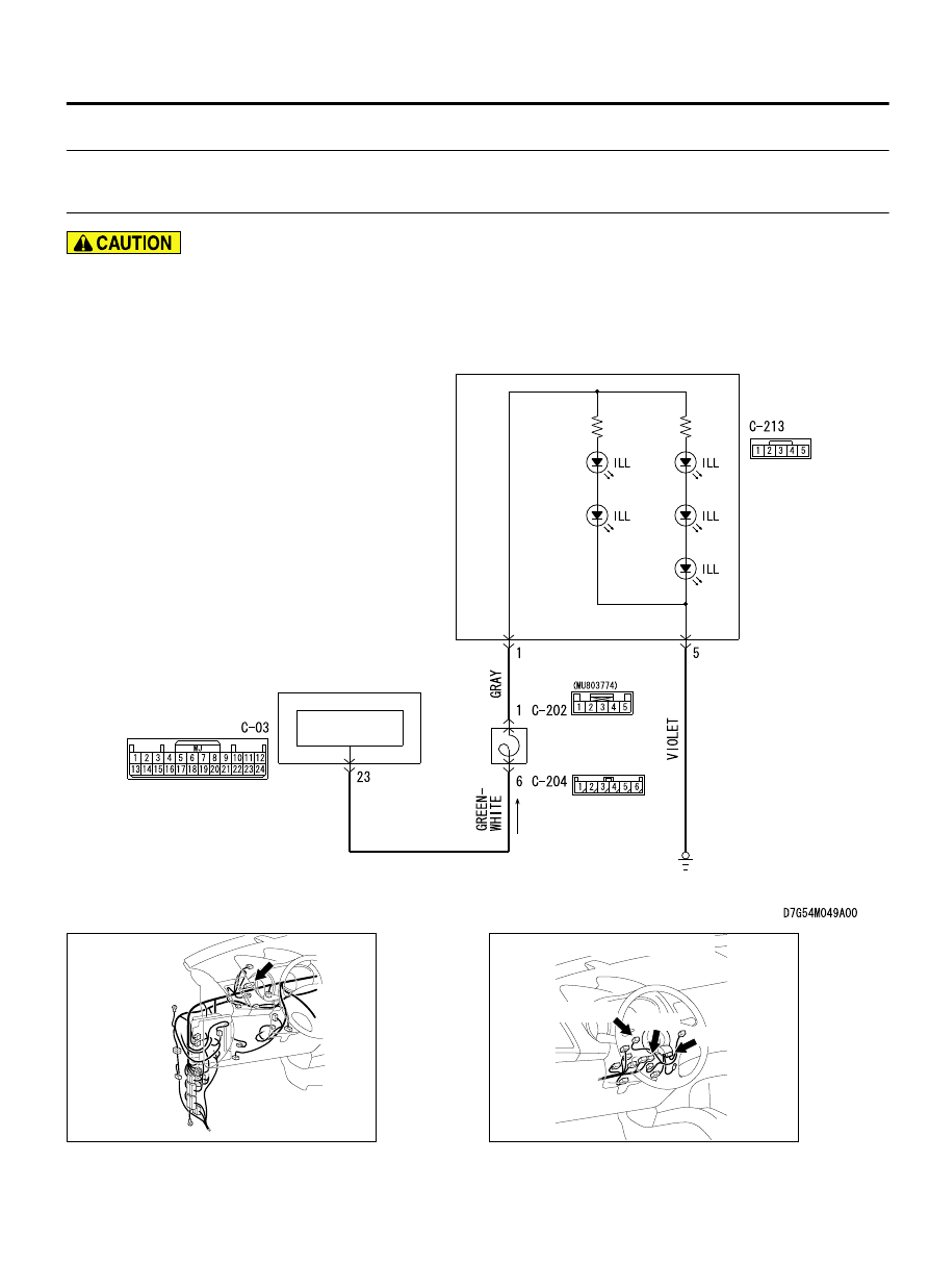
Inspection Procedure 3: The illumination of the steering remote control switch does
not come on.

M15410800373USA0000010000

Before replacing the ECU, ensure that the power
supply  circuit,  the  ground  circuit  and  the
communication circuit are normal.

Steering Audio Switch Illumination Circuit

CLOCK
SPRING

STEERING 
AUDIO
SWITCH

INTERFACE
CIRCUIT

COMBINATION
METER

ZC6008750015

Connector: C-03

ZC6008770003

Connectors: C-202, C-204, C-213

C-213 (R)

C-202

C-204

AUDIO AND NAVIGATION SYSTEM

54B-133

DIAGNOSIS


TECHNICAL DESCRIPTION (COMMENT)
The power supply circuit to the steering remote control
switch,  the  steering  remote  control  switch,  the
combination  meter,  or  the  clock  spring  may  be
defective.

TROUBLESHOOTING HINTS

Malfunction of steering remote control switch

Malfunctions of combination meter

Malfunction of the clock spring

Damaged harness wires and connectors

DIAGNOSIS

Required Special Tools:

MB991223: Harness Set

MB992006: Extra Fine Probe

MB991958: Scan Tool (M.U.T.-III Sub Assembly)

MB991824: Vehicle Communication Interface (V.C.I.)

MB991827: M.U.T.-III USB Cable

MB991910: M.U.T.-III Main Harness A

STEP 1. Check the combination metre.
Check whether the combination meter works normally.

Q:Does the combination meter operate normally?

YES:

 Go to Step 2.

NO:

 Diagnose the combination meter. (Refer to GROUP 54Ab,

Diagnosis P.54Ab-40.)

STEP 2. Check steering remote control switch connector
C-213 for loose, corroded or damaged terminals, or
terminals pushed back in the connector.

Q:Is  steering  remote  control  switch  connector  C-213  in

good condition?

YES:

 Go to Step 3.

NO:

 Repair or replace the damaged component(s). Refer to

GROUP 00E, Harness Connector Inspection P.00E-2. The
steering remote control switch should work normally.

STEP 3. Check the wiring harness between steering remote
control switch connector C-213 (terminal 5) and ground.

Check the ground wire.

Q:Is  the  wiring  harness  between  steering  remote  control

switch connector C-213 (terminal 5) and ground in good

condition?

YES:

 Go to Step 4.

NO:

 The wiring harness may be damaged or the connector

(s) may have loose, corroded or damaged terminals, or
terminals pushed back in the connector. Repair the wiring
harness as necessary.

STEP 4. Check clock spring connectors C-202 and C-204 for
loose, corroded or damaged terminals, or terminals pushed
back in the connector.

Q:Are  clock  spring  connectors  C-202  and  C-204  in  good

condition?

YES:

 Go to Step 5.

54B-134

AUDIO AND NAVIGATION SYSTEM

DIAGNOSIS

NO:

 Repair or replace the damaged component(s). Refer to

GROUP 00E, Harness Connector Inspection P.00E-2. The
steering remote control switch should work normally.

STEP 5. Check the clock spring.
Check whether the clock spring is in good condition (Refer to
GROUP 52B, Air bag module and clock spring P.52B-336).

Q:Is the check result normal?

YES:

 Go to Step 6.

NO:

 Replace the clock spring.

STEP 6. Check the wiring harness between steering remote
control switch connector C-213 (terminal 1) and clock
spring connector C-202 (terminal 1).

Check the power supply lines.

Q:Is  the  wiring  harness  between  steering  remote  control

switch  connector  C-213  (terminal  1)  and  clock  spring

connector C-202 (terminal 1) in good condition?

YES:

 Go to Step 7.

NO:

 The wiring harness may be damaged or the connector

(s) may have loose, corroded or damaged terminals, or
terminals pushed back in the connector. Repair the wiring
harness as necessary.

STEP 7. Check combination meter connector C-03 for loose,
corroded or damaged terminals, or terminals pushed back
in the connector.

Q:Is combination meter connector C-03 in good condition?

YES:

 Go to Step 8.

NO:

 Repair or replace the damaged component(s). Refer to

GROUP 00E, Harness Connector Inspection P.00E-2. The
steering remote control switch should work normally.

STEP 8. Check the wiring harness between combination
meter connector C-03 (terminal 23) and clock spring
connector C-204 (terminal 6).

Check the power supply lines.

Q:Is  the  wiring  harness  between  combination  meter

connector C-03 (terminal 23) and clock spring connector

C-204 (terminal 6) in good condition?

YES:


Go to Step 9.

NO:

 The wiring harness may be damaged or the connector

(s) may have loose, corroded or damaged terminals, or
terminals pushed back in the connector. Repair the wiring
harness as necessary.

STEP 9. Retest the system
Check  whether  the  illumination  of  the  steering  remote  control
switch comes on normally.

Q:Doe the illumination of the steering remote control switch

comes on normally?

AUDIO AND NAVIGATION SYSTEM

54B-135

DIAGNOSIS

YES:

 The trouble can be an intermittent malfunction

(Refer to GROUP 00, How to use Troubleshooting/inspection
Service Points, How to Cope with Intermittent
Malfunction P.00-15).

NO:

 Replace the steering remote control switch.

DIAGNOSIS

STANDARD FLOW OF DIAGNOSTIC TROUBLESHOOTING

M15410800006USA0000010000

Refer  to  GROUP  00  -  Troubleshooting  contents  P.
00-6.

TROUBLE SYMPTOM CHART

M15410800007USA0000010004

Trouble symptom

Inspection
Procedure No.

Reference page

A satellite radio cannot be received.

1

 P.54B-136

Check the satellite radio tuner power supply circuit.

2

 P.54B-139

SYMPTOM PROCEDURES

Inspection Procedure 1: A satellite radio cannot be received.

M15410800375USA0000010000

Before  replacing  the  satellite  radio  tuner,  radio
and  CD  changer  <vehicles  with  radio  and  CD
changer>  or  audio  visual  navigation  unit
<vehicles  with  MMCS>,  ensure  that  the  power
supply  circuit,  the  ground  circuit  and  the
communication circuit are normal.

ZC6008760026

Connectors: C-06, C-14, C-15, C-111

C-06

C-14, C-15

C-111


COMMENTS ON TROUBLE SYMPTOM
There may be a failure in the wiring harness from the
satellite  radio  tuner  to  the  radio  and  CD  changer
<vehicles with radio and CD changer> or audio visual
navigation unit <vehicles with MMCS>, its respective
connector(s), the satellite radio tuner, the CD changer
<vehicles with radio and CD changer> or the audio
visual navigation unit <vehicles with MMCS>.

PROBABLE CAUSES

Malfunctions of satellite radio tuner

Malfunctions  of  changer  <vehicles  with  radio  and
CD  changer>  or  audio  visual  navigation  unit
<vehicles with MMCS>

Damaged harness wires and connectors

54B-136

AUDIO AND NAVIGATION SYSTEM

DIAGNOSIS


Content   ..  1111  1112  1113  1114   ..