Mitsubishi Outlander XL. Manual - part 1075


  Index      Mitsubishi     Mitsubishi Outlander XL - service repair manual 2007 year


Search            


Content   ..  1073  1074  1075  1076   ..


Mitsubishi Outlander XL. Manual - part 1075


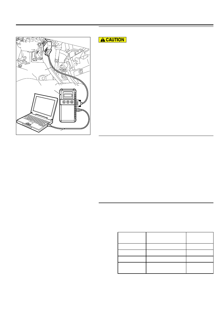
STEP 1. Using scan tool MB991958, diagnose the CAN bus
line.

ZC501967

AC404789

ZC5019680000

MB991824

MB991827

MB991910

Data link

connector

To prevent damage to scan tool MB991958, always turn the
ignition  switch  to  the  "LOCK"  (OFF)  position  before
connecting or disconnecting scan tool MB991958.

(1)

Connect scan tool MB991958. Refer to "How to connect the
scan tool (M.U.T.-III) P.54Af-4."

(2)

Turn the ignition switch to the "ON" position.

(3)

Diagnose the CAN bus line.

(4)

Turn the ignition switch to the "LOCK" (OFF) position.

Q:Is the CAN bus line found to be normal?

YES:

 Go to Step 2.

NO:

 Repair the CAN bus line (Refer to GROUP 54D,

Diagnosis P.54D-17).

STEP 2. Using scan tool MB991958, check for any
diagnostic trouble code.
Check if DTC is set to the KOS-ECU <vehicles with KOS> or
WCM <vehicles with WCM>.

(1)

Turn the ignition switch to the "ON" position.

(2)

Check whether the KOS or WCM related DTC is set.

(3)

Turn the ignition switch to the "LOCK" (OFF) position.

Q:Is the DTC set?

YES<vehicles with KOS>:

 Troubleshoot the KOS (Refer to

GROUP 42B, KOS P.42B-18).

YES<vehicles with WCM>:

 Troubleshoot the WCM (Refer to

GROUP 42C, WCM P.42C-11).

NO:

 Go to Step 3.

STEP 3. Using scan tool MB991958, check data list.
Use the ETACS-ECU data list to check the signals related to the
ignition key cylinder illumination light function.

Turn the ignition switch to the "LOCK" (OFF) position.

Remove the ignition key from the ignition key cylinder.

Open the driver's door.

Item No.

Item name

Normal
conditions

Item 228

Dr door unlock

ON

Item 254

IG voltage

0 V

Item 256

Dr door ajar switch

ON

Item 264

Handle lock switch

Key in → Key
out

IGNITION SWITCH

54Ag-11

SYMPTOM PROCEDURES

Q:Does  scan  tool  MB991958  display  the  items  "Dr  door

unlock", "Dr door ajar switch", and "Handle lock switch"

as normal condition?

YES<Normal conditions are displayed for all the
items.>:

 Go to Step 4.

NO<Normal condition is not displayed for item No.
228.>:

 Troubleshoot the ETACS-ECU. Refer to GROUP 54Ad,

Diagnosis - Inspection Procedure 4 "ETACS-ECU does not
receive any signal from the front door lock actuator" P.
54Ad-67.

NO<Normal condition is not displayed for item No.
254.>:

 Troubleshoot the ETACS-ECU. Refer to GROUP 54Ad,

Diagnosis - Inspection Procedure 2 "ETACS-ECU does not
receive any signal from the ignition switch (IG1)" P.
54Ad-62.

NO<Normal condition is not displayed for item No.
256.>:

 Troubleshoot the ETACS-ECU. Refer to GROUP 54Ad,

Diagnosis - Inspection Procedure 6 "ETACS-ECU does not
receive any signal from the front the front door switch
(RH)" P.54Ad-75.

NO<Normal condition is not displayed for item No.
264.>:

 Troubleshoot the ETACS-ECU. Refer to GROUP 54Ad,

Diagnosis - Inspection Procedure 3 "ETACS-ECU does not
receive any signal from key reminder switch" P.54Ad-64.

STEP 4. Check key reminder switch connector C-211,
ETACS-ECU connector C-315 for loose, corroded or
damaged terminals, or terminals pushed back in the
connector.

Q:Is  key  reminder  switch  connector  C-211,  ETACS-ECU

connector C-315 in good condition?

YES:

 Go to Step 5.

NO:

 Repair the damaged parts.

STEP 5. Check the Wiring harness between key reminder
switch connector C-211 (terminal No. 3,5) and ETACS-ECU
connector C-315 (terminal No. 13,18).

Check the input/output line for open circuit.

Q:Is the check result normal?

YES:

 Go to Step 6.

NO:

 Repair the wiring harness between key reminder switch

connector C-211 and ETACS-ECU connector C-315.

STEP 6. Check of ignition key cylinder illumination light
bulb.

Q:Is the ignition key cylinder illumination light bulb in good

condition?

YES:

 Go to Step 7.

NO:

 Replace the bulb of the ignition key cylinder

illumination light.

54Ag-12

IGNITION SWITCH

SYMPTOM PROCEDURES

STEP 7. Retest the system.

Q:Does  the  ignition  key  cylinder  illumination  light

illuminate/extinguish in good condition?

YES:

 The trouble can be an intermittent malfunction

(Refer to GROUP 00, How to use Troubleshooting/inspection
Service Points - How to Cope with Intermittent
Malfunction P.00-15).

NO:

 Replace the ETACS-ECU.

ON-VEHICLE SERVICE

CHECK OF IGNITION KEY REMINDER WARNING

FUNCTION (STEERING LOCK REMINDER TONE

ALARM BY KOS)

M15410000010USA0000010000

1.

Driver's door: Release the closed and steering wheel lock, or
turn the ignition key vehicles with WCM or emergency key
vehicles  with  KOS  to  the  "LOCK"  (OFF)  position  (key
inserted).

2.

Change the driver's door state from closed to open.

3.

Check that the tone alarm sounds normally.

4.

If a malfunction is found, carry out the troubleshooting (Refer
to  GROUP  54Ab,  Combination  Meter  -  Trouble  Symptom
Chart P.54Ab-40).

REMOVAL AND INSTALLATION

M15410000011USA0000010000

To  remove  the  driver  airbag  module,  refer  to
GROUP  52B  -  Service  Precautions  P.52B-28
and
Air Bag Module(s) and Clock Spring P.52B-329.

Pre-removal Operation

Removal of lower panel and steering column cover (Refer to

GROUP 52A - Instrument Panel Assembly P.52A-2.)

Removal  of  clock  spring/column  switch  assembly  (Refer  to

GROUP 37 - Steering Shaft P.37-23and GROUP 52B - Air Bag

Module(s) and Clock Spring P.52B-329.)

Post-installation Operation

Installation of clock spring/column switch assembly (Refer to

GROUP 37 - Steering Shaft P.37-23and GROUP 52B - Air Bag

Module(s) and Clock Spring P.52B-329.)

Installation of lower panel and steering column cover (Refer to

GROUP 52A - Instrument Panel Assembly P.52A-2.)

IGNITION SWITCH

54Ag-13

ON-VEHICLE SERVICE

ZC600982

ZC600408

ZC600409

<Vehicles with KOS>

2

1

3

<Vehicles with WCM>

1

3

5

4

4

AA00

2.0 ± 0.5 N·m 
18 ± 4 in-lb

2.0 ± 0.5 N·m 
18 ± 4 in-lb

2

Removal Steps

1.

Ignition switch

2.

Key reminder switch

3.

Key ring illumination light

4.

WCM  <vehicles  with  WCM>/receiver
antenna module <vehicles with KOS>

Removal Steps

<<A>>

5.

Steering  lock  cylinder  <vehicles  with
WCM>

REMOVAL SERVICE POINT

<<A>> STEERING LOCK CYLINDER REMOVAL <VEHICLES
WITH WCM>

1.

Insert  the  key  into  the  steering  lock  cylinder,  and  turn  the
ignition key to the "ACC" position.

54Ag-14

IGNITION SWITCH

REMOVAL AND INSTALLATION


Content   ..  1073  1074  1075  1076   ..