Mitsubishi Outlander XL. Manual - part 1049


  Index      Mitsubishi     Mitsubishi Outlander XL - service repair manual 2007 year


Search            


Content   ..  1047  1048  1049  1050   ..


Mitsubishi Outlander XL. Manual - part 1049


STEP 5. Check the wiring harness between driver's door
switch connector D-23 (terminal 3) and ETACS-ECU
connector C-313 (terminal 16).

Q:Is  the  wiring  harness  between  driver's  door  switch

connector D-23 (terminal 3) and ETACS-ECU connector

C-313 (terminal 16) in good condition?

YES:

 Replace the ETACS-ECU. Check that the input signal

of front door switch (LH) is normal.

NO:

 The wiring harness may be damaged or the connector

(s) may have loose, corroded or damaged terminals, or
terminals pushed back in the connector. Repair the wiring
harness as necessary. Check that the input signal of front
door switch (LH) is normal.

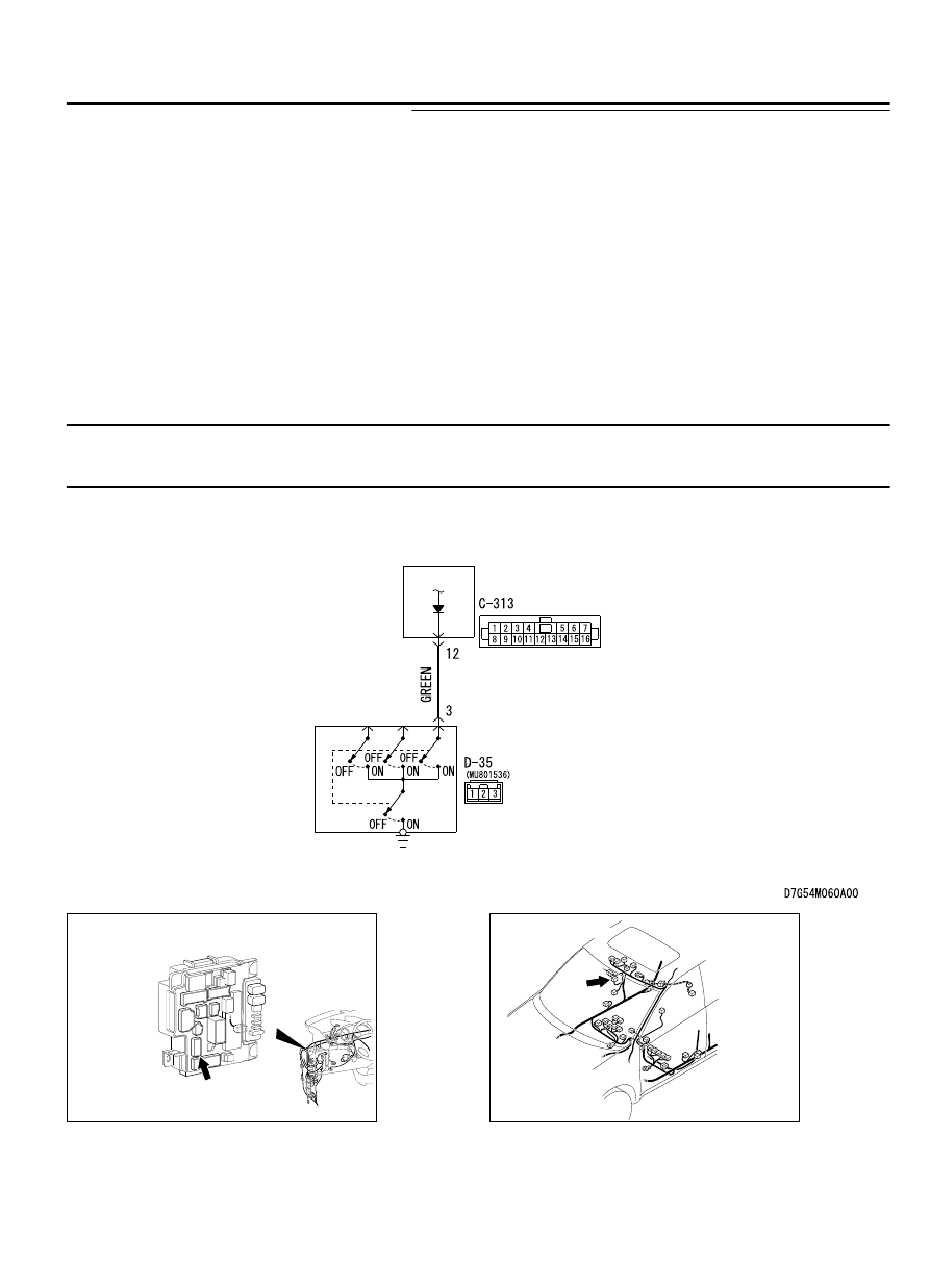
Inspection Procedure 6: ETACS-ECU does not receive any signal from the front door
switch (RH).

M15410600069USA0000010000

ETACS-
ECU

FRONT DOOR
SWITCH (RH)

Front Door Switch (RH) Input Circuit

ZC6008780018

Connector: C-313

C-313 (BR)

ZC6008790008

Connector: D-35

ETACS

54Ad-75

DIAGNOSIS

TECHNICAL DESCRIPTION (COMMENT)
If there is an error to the front door switch (RH) input
signal, the front door switch (RH) signal is no longer
output to the communication line.

TROUBLESHOOTING HINTS

The front door switch (RH) may be defective

The ETACS-ECU may be defective

The wiring harness or connectors may have loose,
corroded,  or  damaged  terminals,  or  terminals
pushed back in the connector

DIAGNOSIS

Required Special Tools:

MB991223: Harness Set

MB992006: Extra Fine Probe

STEP 1. Check front door switch (RH) connector D-35 for
loose, corroded or damaged terminals, or terminals pushed
back in the connector.

Q:Is  front  door  switch  (RH)  connector  D-35  in  good

condition?

YES:

 Go to Step 2.

NO:

 Repair or replace the damaged component(s). Refer to

GROUP 00E, Harness Connector Inspection P.00E-2. Check
that the input signal of front door switch (RH) is normal.

STEP 2. Check the front door switch (RH).
Remove the front door switch (RH). Then check the continuity
between the switch terminals and the switch body.

Switch position

Tester
connection

Specified condition

Released

3 - switch body

Less than 2 ohms

Pressed

3 - switch body

Open circuit

Q:Is the front door switch (RH) in good condition?

YES:

 Go to Step 3.

NO:

 Replace the front door switch (RH). Check that the

input signal of front door switch (RH) is normal.

STEP 3. Measure at the lower metal part of the front door
switch (RH) in order to check the ground circuit to the front
door switch (RH).

NOTE: 

Check that the front door switch (RH) is grounded to

the vehicle body by means of its mounting screw.
Remove the cap, and measure the resistance value between the
lower metal part and the ground.

The resistance should equal 2 ohms or less.

Q:Is the measured resistance 2 ohms or less?

YES:

 Go to Step 4.

NO:

 Check the fit of the switch, and repair if necessary.

Check that the input signal of front door switch (RH) is
normal.

54Ad-76

ETACS

DIAGNOSIS

STEP 4. Check ETACS-ECU connector C-313 for loose,
corroded or damaged terminals, or terminals pushed back
in the connector.

Q:Is ETACS-ECU connector C-313 in good condition?

YES:

 Go to Step 5.

NO:

 Repair or replace the damaged component(s). Refer to

GROUP 00E, Harness Connector Inspection P.00E-2. Check
that the input signal of front door switch (RH) is normal.

STEP 5. Check the wiring harness between front door
switch (RH) connector D-35 (terminal 3) and ETACS-ECU
connector C-313 (terminal 12).

Q:Is  the  wiring  harness  between  driver's  door  switch

connector D-35 (terminal 3) and ETACS-ECU connector

C-313 (terminal 12) in good condition?

YES:

 Replace the ETACS-ECU. Check that the input signal

of front door switch (RH) is normal.

NO:

 The wiring harness may be damaged or the connector

(s) may have loose, corroded or damaged terminals, or
terminals pushed back in the connector. Repair the wiring
harness as necessary. Check that the input signal of front
door switch (RH) is normal.

Inspection Procedure 7: ETACS-ECU does not receive any signal from the rear door
switch (LH).

M15410600072USA0000010000

ETACS-
ECU

REAR DOOR
SWITCH (LH)

Rear Door Switch (LH) Input Circuit

ETACS

54Ad-77

DIAGNOSIS

ZC6008780018

Connector: C-313

C-313 (BR)

ZC6008800009

Connector: D-17

TECHNICAL DESCRIPTION (COMMENT)
If there is an error to the rear door switch (LH) input
signal, the rear door switch (LH) signal is no longer
output to the communication line.

TROUBLESHOOTING HINTS

The rear door switch (LH) may be defective

The ETACS-ECU may be defective

The wiring harness or connectors may have loose,
corroded,  or  damaged  terminals,  or  terminals
pushed back in the connector

DIAGNOSIS

Required Special Tools:

MB991223: Harness Set

MB992006: Extra Fine Probe

STEP 1. Check rear door switch (LH) connector D-17 for
loose, corroded or damaged terminals, or terminals pushed
back in the connector.

Q:Is  rear  door  switch  (LH)  connector  D-17  in  good

condition?

YES:

 Go to Step 2.

NO:

 Repair or replace the damaged component(s). Refer to

GROUP 00E, Harness Connector Inspection P.00E-2. Check
that the input signal of rear door switch (LH) is normal.

STEP 2. Check the rear door switch (LH).
Remove the rear door switch (LH). Then check the continuity
between the switch terminals and the switch body.

Switch position

Tester
connection

Specified condition

Released

3 - switch body

Less than 2 ohms

Pressed

3 - switch body

Open circuit

Q:Is the rear door switch in good condition?

YES:

 Go to Step 3.

NO:

 Replace the rear door switch (LH). Check that the

input signal of rear door switch (LH) is normal.

54Ad-78

ETACS

DIAGNOSIS


Content   ..  1047  1048  1049  1050   ..