Mitsubishi Outlander XL. Manual - part 1016


  Index      Mitsubishi     Mitsubishi Outlander XL - service repair manual 2007 year


Search            


Content   ..  1014  1015  1016  1017   ..


Mitsubishi Outlander XL. Manual - part 1016


damaged terminals, or terminals pushed back in the
connector.

Q:Is  daytime  running  light  (LH)  connector  A-42,  daytime

running light (RH) A-52 in good condition?

YES:

 Go to Step 2.

NO:

 Repair the damaged parts.

STEP 2. Check the daytime running light bulb.

(1)

Remove the daytime running light bulb.

(2)

Verify that the daytime running light bulb is not damaged or
burned out.

Q:Is the daytime running light bulb in good condition?

YES:

 Go to Step 3.

NO:

 Replace the daytime running light bulb. Verify that

the daytime running lights illuminate normally.

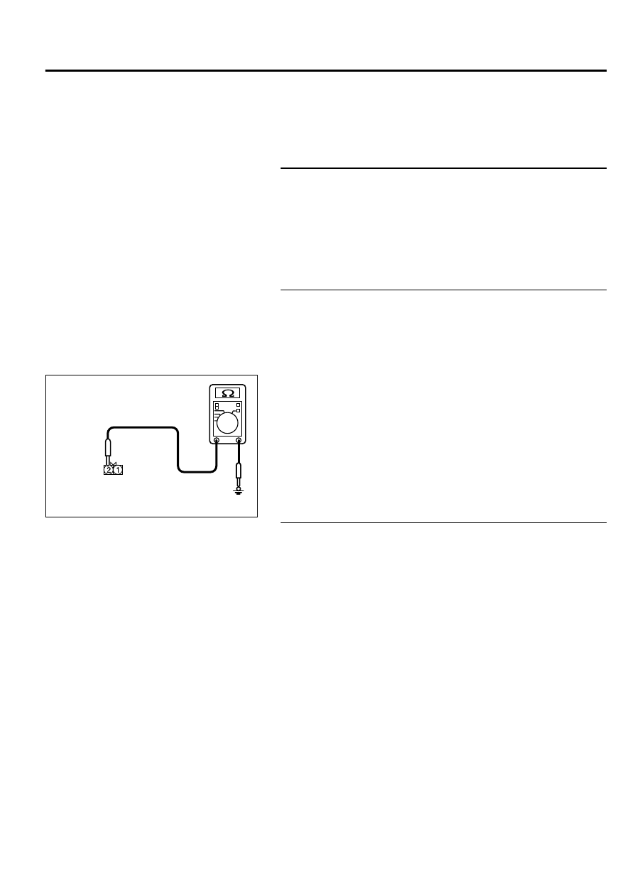
Step 3. Check the ground circuit to the daytime running light
(LH) or daytime running light (RH). Measure the resistance
at daytime running light (LH) connector A-42 or daytime
running light (RH) connector A-52.

(1)

Disconnect the connector, and measure at the wiring harness
side.

ZC5010410047

Connectors A-42, A-52  
(Harness side)

(2)

Check  the  resistance  between  the  daytime  running  light
connector and ground.

Resistance  between  A-42  daytime  running  light  (LH)
connector terminal No.2 and ground

Resistance  between  A-52  daytime  running  light  (RH)
connector terminal No.2 and ground

OK: The resistance should be 2 ohm or less.

Q:Is the measured resistance 2 ohms or less?

YES:

 Go to Step 5.

NO:

 Go to Step 4.

Step 4. Check the wiring harness between daytime running
light (LH) connector A-42 or daytime running light (RH)
connector A-52 (terminal 1) and ground.

NOTE: 

Also check intermediate connector A-47 for loose,

corroded, or damaged terminals, or terminals pushed back in
the connector. If intermediate connector A-47 is damaged,
repair or replace the connector as described in GROUP 00E,
Harness Connector Inspection P.00E-2.

Check the ground wires for open circuit.

Q:Is the wiring harness between daytime running light (LH)

connector A-42 or daytime running light (RH) connector

A-52 (terminal 1) and ground in good condition?

YES:

 The trouble can be an intermittent malfunction

(Refer to GROUP 00 - How to Cope with Intermittent
Malfunction P.00-15).

NO:

 Repair the wiring harness.

LIGHTING

54Ac-137

DIAGNOSIS

STEP 5. Check daytime running light relay connector A-23X
for loose, corroded or damaged terminals, or terminals
pushed back in the connector.

Q:Is daytime running light relay connector A-23X in good

condition?

YES:

 Go to Step 6.

NO:

 Repair the damaged parts.

STEP 6. Check the wiring harness between daytime running
light (LH) connector A-42or daytime running light (RH)
connector A-52 (terminal 1) and daytime running light relay
connector A-23X (terminal 3).

NOTE: 

Also check intermediate connector A-47 for loose,

corroded, or damaged terminals, or terminals pushed back in
the connector. If intermediate connector A-47 is damaged,
repair or replace the connector as described in GROUP 00E,
Harness Connector Inspection P.00E-2.

Check the power supply line for open circuit.

Q:Is the wiring harness between daytime running light (LH)

connector A-42 or daytime running light (RH) connector

A-52  (terminal  1)  and  daytime  running  light  relay

connector A-23X (terminal 3) in good condition?

YES:

 Go to Step 7.

NO:

 The wiring harness may be damaged or the connector

(s) may have loose, corroded or damaged terminals, or
terminals pushed back in the connector. Repair the wiring
harness as necessary. Verify that the fog lights
illuminate normally.

STEP 7. Retest the system.

Q:Does  the  right  or  left  daytime  running  light  does  not

illuminate in good condition?

YES:

 The trouble can be an intermittent malfunction

(Refer to GROUP 00, How to use Troubleshooting/inspection
Service Points - How to Cope with Intermittent
Malfunction P.00-15).

NO:

 Replace the daytime running light(s).

DIAGNOSIS

STANDARD FLOW OF DIAGNOSTIC TROUBLESHOOTING

M15410900005USA0000010004

Refer to GROUP 00 - Contents of troubleshooting P.
00-6.

54Ac-138

LIGHTING

DIAGNOSIS

DIAGNOSTIC FUNCTION

M15410900006USA0000010005

HOW TO CONNECT THE SCAN TOOL (M.U.T.-III)

Required Special Tools:

MB991958: Scan Tool (M.U.T.-III Sub Assembly)

MB991824: Vehicle Communication Interface (V.C.I.)

MB991827: M.U.T.-III USB Cable

MB991910:  M.U.T.-III  Main  Harness  A  (Vehicles  with
CAN communication system)

ZC501967

AC404789

ZC5019680000

MB991824

MB991827

MB991910

Data link

connector

To prevent damage to scan tool MB991958, always turn the
ignition  switch  to  the  "LOCK"  (OFF)  position  before
connecting or disconnecting scan tool MB991958.

1.

Ensure that the ignition switch is at the "LOCK" (OFF) position.

2.

Start up the personal computer.

3.

Connect special tool MB991827 to special tool MB991824 and
the personal computer.

4.

Connect special tool MB991910 to special tool MB991824.

5.

Connect special tool MB991910 to the data link connector.

6.

Turn the power switch of special tool MB991824 to the "ON"
position.

NOTE: 

When special tool MB991824 is energized, special

tool MB991824 indicator light will be illuminated in a
green color.

7.

Start the M.U.T.-III system on the personal computer.

NOTE: 

Disconnecting scan tool MB991958 is the reverse of

the connecting sequence, making sure that the ignition
switch is at the "LOCK" (OFF) position.

HOW TO READ AND ERASE DIAGNOSTIC

TROUBLE CODES

Required Special Tools:

MB991958: Scan Tool (M.U.T.-III Sub Assembly)

MB991824: Vehicle Communication Interface (V.C.I.)

MB991827: M.U.T.-III USB Cable

MB991910:  M.U.T.-III  Main  Harness  A  (Vehicles  with
CAN communication system)

To prevent damage to scan tool MB991958, always turn the
ignition  switch  to  the  "LOCK"  (OFF)  position  before
connecting or disconnecting scan tool MB991958.

NOTE: 

If the battery voltage is low, diagnostic trouble

codes will not be set. Check the battery if scan tool
MB991958 does not display.

1.

Connect scan tool MB991958 to the data link connector.

LIGHTING

54Ac-139

DIAGNOSIS

2.

Turn the ignition switch to the "ON" position.

3.

Select "System select" from the start-up screen.

4.

Select "From 2006 MY" of "Model Year." When the "Vehicle
Information" is displayed, check the contents.

5.

Select  "ETACS"  from  "System  List",  and  press  the  "OK"
button.

NOTE: 

When the "Loading Option Setup" list is displayed,

check the applicable item.

6.

Select "Diagnostic Trouble Code."

7.

If a DTC is set, it is shown.

8.

Choose "Erase DTCs" to erase the DTC.

TROUBLE SYMPTOM CHART

M15410900009USA0000010004

Trouble symptom

Inspection
Procedure No.

Reference page

The front dome light does not illuminate normally.

1

 P.54Ac-141

The rear dome light does not illuminate normally.

2

 P.54Ac-146

The luggage compartment light does not illuminate normally.

3

 P.54Ac-150

The foot light does not illuminate normally.

4

 P.54Ac-155

The interior light auto-cut function does not operate correctly.

5

 P.54Ac-158

54Ac-140

LIGHTING

DIAGNOSIS


Content   ..  1014  1015  1016  1017   ..