Mitsubishi Outlander XL. Manual - part 1007


  Index      Mitsubishi     Mitsubishi Outlander XL - service repair manual 2007 year


Search            


Content   ..  1005  1006  1007  1008   ..


Mitsubishi Outlander XL. Manual - part 1007


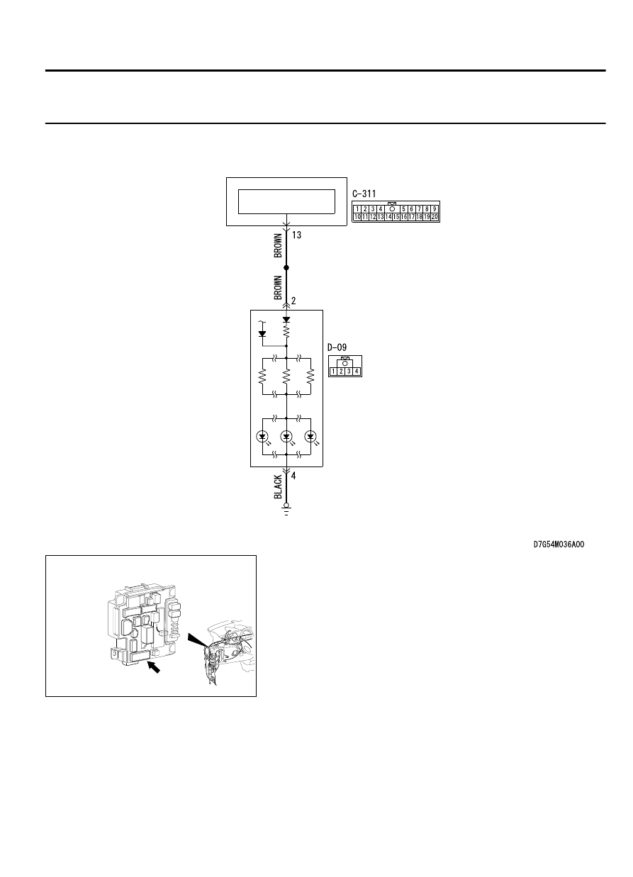
DTC B16A7: Taillight (RH) circuit short

M15410900091USA0000010000

Taillight (RH) Circuit

REAR
COMBINATION
LIGHT  (RH)

ETACS-ECU

TAILLIGHT 
CONTROL CIRCUIT

ZC6008780025

Connector: C-311

LIGHTING

54Ac-101

DIAGNOSIS

ZC6008800018

Connector: D-09

D-09

TROUBLE JUDGMENT
When an open circuit is detected in the taillight circuit,
the ETACS-ECU sets DTC B16A0. If a short circuit is
detected, DTC B16A7 is set.

TECHNICAL DESCRIPTION (COMMENT)
The problem detection of taillight is made based on
the digital feed back signal (input signal to ETACS-
ECU) which operates the taillight. When the ignition
switch  is  "ON",  the  ETACS-ECU  determines  the
taillight circuit state from the load placed on the line.
After 100 ms has elapsed since the start of the check,
the ETACS-ECU performs a sampling with each 10

ms.  If  an  abnormality  is  detected,  it  increases  the
counter by 2, and when no abnormality is detected, it
decreases  the  counter  by  1.  Once  the  counter
reaches "10", the ETACS-ECU sets the DTC B16A0
if the load is detected on the line, and sets the DTC
B16A7 if no load is detected.

TROUBLESHOOTING HINTS

The wiring harness or connectors may have loose,
corroded,  or  damaged  terminals,  or  terminals
pushed back in the connector

Malfunction of the ETACS-ECU

DIAGNOSIS

Required Special Tools:

MB992006: Extra fine probe

MB991223: Harness set

MB991958: Scan Tool (M.U.T.-III Sub Assembly)

MB991824: Vehicle Communication Interface (V.C.I.)

MB991827: M.U.T.-III USB Cable

MB991910:  M.U.T.-III  Main  Harness  A  (Vehicles  with
CAN communication system)

STEP 1. Check rear combination light (RH) connector D-09
for loose, corroded or damaged terminals, or terminals
pushed back in the connector.

Q:Is  combination  light  (RH)  connector  D-09  in  good

condition?

YES:

 Go to Step 2.

NO:

 Repair the damaged parts.

STEP 2. Resistance measurement at rear combination light
(RH) connector D-09.

(1)

Disconnect the connector, and measure at the wiring harness
side.

54Ac-102

LIGHTING

DIAGNOSIS

ZC5015310002

Connector D-09 
(Harness side)

(2)

Measure the resistance between rear combination light (RH)
connector D-09 (terminal No. 4) and the body ground.

The measured value should be continuity exists (2
Ω or less).

Q:Does the measured resistance value correspond with this

range?

YES:

 Go to Step 4.

NO:

 Go to Step 3.

STEP 3. Check the wiring harness between rear
combination light (RH) connector D-09 (terminal No. 4) and
ground.

Q:Is the wiring harness between rear combination light (RH)

connector  D-09  (terminal  No.  4)  and  ground  in  good

condition?

YES:

 Go to Step 6.

NO:

 Repair the wiring harness.

STEP 4. Check ETACS-ECU connectors C-311 for loose,
corroded or damaged terminals, or terminals pushed back
in the connector.

Q:Is ETACS-ECU connectors C-311 in good condition?

YES:

 Go to Step 5.

NO:

 Repair the damaged parts.

STEP 5. Check the wiring harness between rear
combination light (RH) D-09 connector (terminal No. 2) and
ETACS-ECU connector C-311 (terminal No. 13).

Q:Is the wiring harness between rear combination light (RH)

D-09  connector  (terminal  No.  2)  and  ETACS-ECU

connector C-311 (terminal No. 13) in good condition?

YES:

 Go to Step 6.

NO:

 Repair the wiring harness.

LIGHTING

54Ac-103

DIAGNOSIS

STEP 6. Using scan tool MB991958, Check whether the
diagnostic trouble code is reset.

ZC501967

AC404789

ZC5019680000

MB991824

MB991827

MB991910

Data link

connector

To prevent damage to scan tool MB991958, always turn the
ignition  switch  to  the  "LOCK"  (OFF)  position  before
connecting or disconnecting scan tool MB991958.

(1)

Connect scan tool MB991958. Refer to "How to connect scan
tool P.54Ac-99."

(2)

Turn the ignition switch to the "ON" position.

(3)

Erase the DTC.

(4)

Turn the ignition switch from "LOCK" (OFF) position to "ON"
position.

(5)

Check if DTC is set.

Q:Is the DTC set?

YES:

 Replace the ETACS-ECU.

NO:

 The procedure is complete.

DTC B16A1: Taillight (LH) circuit open

54Ac-104

LIGHTING

DIAGNOSIS


Content   ..  1005  1006  1007  1008   ..