Mitsubishi Outlander XL. Manual - part 1006


  Index      Mitsubishi     Mitsubishi Outlander XL - service repair manual 2007 year


Search            


Content   ..  1004  1005  1006  1007   ..


Mitsubishi Outlander XL. Manual - part 1006


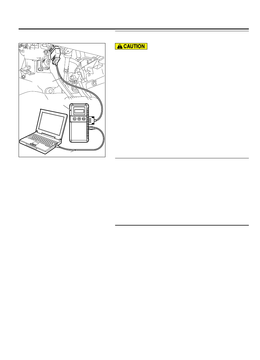
STEP 1. Using scan tool MB991958, read the diagnostic
trouble code.

ZC501967

AC404789

ZC5019680000

MB991824

MB991827

MB991910

Data link

connector

To prevent damage to scan tool MB991958, always turn the
ignition  switch  to  the  "LOCK"  (OFF)  position  before
connecting or disconnecting scan tool MB991958.

(1)

Connect scan tool MB991958. Refer to "How to connect scan
too (M.U.T.-III) P.54Ac-58."

(2)

Turn the ignition switch to the "ON" position.

(3)

Check whether the headlight automatic leveling-ECU related
DTC is set.

(4)

Turn the ignition switch to the "LOCK" (OFF) position.

Q:Is DTC set?

YES:

 Perform the troubleshooting of when the diagnostic

trouble code is set (Refer to P.54Ac-59).

NO:

 Go to Step 2.

STEP 2. Using scan tool MB991958, check other system
actuator test.
Perform the actuator test for the combination meter, and check
that the headlight automatic leveling warning is displayed.

(1)

Turn the ignition switch to the "ON" position.

(2)

Set scan tool MB991958 to the actuator test mode.

Item 8: Indicator2

(3)

Turn the ignition switch to the "LOCK" (OFF) position.

Q:Is the check result normal?

YES:

 Go to Step 3.

NO:

 Replace the combination meter.

STEP 3. Retest the system.
Check whether the headlight automatic leveling warning display
goes out.

Q:Is the check result normal?

YES:

 The trouble can be an intermittent malfunction

(Refer to GROUP 00 - How to use Troubleshooting/
inspection Service Points - How to Cope with Intermittent
Malfunction P.00-15).

NO:

 Replace the headlight automatic leveling-ECU.

HEADLIGHT AUTOMATIC LEVELING ECU TERMINAL VOLTAGE

M15410900034USA0000010000

LIGHTING

54Ac-97

DIAGNOSIS

ZC603878

C-110

0000

Terminal
No.

Check item

Check conditions

Normal conditions

1

Power  supply  from  ignition  switch
(IG1)

Ignition switch: ON

Battery voltage

2

Headlight  leveling  unit  (LH)  power
supply

Ignition switch: ON

Battery voltage

3

Output to the headlight leveling unit
(LH)

Ignition switch: ON

1.2 - 10.8 V

4

Headlight leveling unit (LH) ground Always

0 V

5

Output of diagnosis signal

At  reading  of  diagnostic  trouble
code

1.5 V or less

6

Headlight relay ON signal

Headlight: ON

Battery voltage

7

Output of the pulse check signal

Ignition switch: ON

0 - 12 V (pulse signal)

8

Headlight

 automatic

 leveling

warning display output

Ignition switch: ON
Warning display illumination

1.2 V or less

9

Input of vehicle speed signal

Perform a test run of the vehicle. 0 - 12 V (pulse signal)

11

Headlight  leveling  unit  (RH)  power
supply

Ignition switch: ON

Battery voltage

12

Output to the headlight leveling unit
(RH)

Ignition switch: ON

1.2 - 10.8 V

13

Headlight leveling unit (RH) ground Always

0 V

14

Ground

Always

0 V

15

Front height sensor power supply

Ignition switch: ON

5 V

16

Rear height sensor power supply

Ignition switch: ON

5 V

17

Input from front height sensor

Ignition switch: ON

0.5 - 4.5 V

18

Input from the rear height sensor

Ignition switch: ON

0.5 - 4.5 V

19

Front height sensor ground

Always

0 V

20

Rear height sensor ground

Always

0 V

DIAGNOSIS

STANDARD FLOW OF DIAGNOSTIC TROUBLESHOOTING

M15410900005USA0000010002

Refer to GROUP 00 - Contents of troubleshooting P.
00-6.

54Ac-98

LIGHTING

DIAGNOSIS

DIAGNOSTIC FUNCTION

M15410900006USA0000010002

HOW TO CONNECT THE SCAN TOOL (M.U.T.-III)

Required Special Tools:

MB991958: Scan Tool (M.U.T.-III Sub Assembly)

MB991824: Vehicle Communication Interface (V.C.I.)

MB991827: M.U.T.-III USB Cable

MB991910:  M.U.T.-III  Main  Harness  A  (Vehicles  with
CAN communication system)

ZC501967

AC404789

ZC5019680000

MB991824

MB991827

MB991910

Data link

connector

To prevent damage to scan tool MB991958, always turn the
ignition  switch  to  the  "LOCK"  (OFF)  position  before
connecting or disconnecting scan tool MB991958.

1.

Ensure that the ignition switch is at the "LOCK" (OFF) position.

2.

Start up the personal computer.

3.

Connect special tool MB991827 to special tool MB991824 and
the personal computer.

4.

Connect special tool MB991910 to special tool MB991824.

5.

Connect special tool MB991910 to the data link connector.

6.

Turn the power switch of special tool MB991824 to the "ON"
position.

NOTE: 

When special tool MB991824 is energized, special

tool MB991824 indicator light will be illuminated in a
green color.

7.

Start the M.U.T.-III system on the personal computer.

NOTE: 

Disconnecting scan tool MB991958 is the reverse of

the connecting sequence, making sure that the ignition
switch is at the "LOCK" (OFF) position.

HOW TO READ AND ERASE DIAGNOSTIC

TROUBLE CODES

Required Special Tools:

MB991958: Scan Tool (M.U.T.-III Sub Assembly)

MB991824: Vehicle Communication Interface (V.C.I.)

MB991827: M.U.T.-III USB Cable

MB991910:  M.U.T.-III  Main  Harness  A  (Vehicles  with
CAN communication system)

To prevent damage to scan tool MB991958, always turn the
ignition  switch  to  the  "LOCK"  (OFF)  position  before
connecting or disconnecting scan tool MB991958.

NOTE: 

If the battery voltage is low, diagnostic trouble

codes will not be set. Check the battery if scan tool
MB991958 does not display.

1.

Connect scan tool MB991958 to the data link connector.

LIGHTING

54Ac-99

DIAGNOSIS

2.

Turn the ignition switch to the "ON" position.

3.

Select "System select" from the start-up screen.

4.

Select "From 2006 MY" of "Model Year." When the "Vehicle
Information" is displayed, check the contents.

5.

Select  "ETACS"  from  "System  List",  and  press  the  "OK"
button.

NOTE: 

When the "Loading Option Setup" list is displayed,

check the applicable item.

6.

Select "Diagnostic Trouble Code."

7.

If a DTC is set, it is shown.

8.

Choose "Erase DTCs" to erase the DTC.

DIAGNOSTIC TROUBLE CODE CHART

M15410900007USA0000010002

On troubleshooting, if the ignition switch is turned
ON while disconnecting connector(s), diagnostic
trouble code(s) associated with other system may

be  set.  On  completion,  confirm  all  systems  for
diagnostic  trouble  code(s).  If  diagnostic  trouble
code(s) are set, erase them all.

Diagnostic  trouble  code
No.

Diagnostic item

Reference page

B16A0

Taillight (RH) circuit open

 P.54Ac-100

B16A7

Taillight (RH) circuit short

 P.54Ac-100

B16A1

Taillight (LH) circuit open

 P.54Ac-104

B16A8

Taillight (LH) circuit short

 P.54Ac-104

DIAGNOSTIC TROUBLE CODE PROCEDURES

DTC B16A0: Taillight (RH) circuit open

54Ac-100

LIGHTING

DIAGNOSIS


Content   ..  1004  1005  1006  1007   ..