Mitsubishi Outlander XL. Manual - part 67


  Index      Mitsubishi     Mitsubishi Outlander XL - service repair manual 2007 year


Search            


Content   ..  65  66  67  68   ..


Mitsubishi Outlander XL. Manual - part 67


HOW TO READ CONFIGURATION DIAGRAMS

CONFIGURATION DIAGRAMS

80A-3

HOW TO READ CONFIGURATION DIAGRAMS

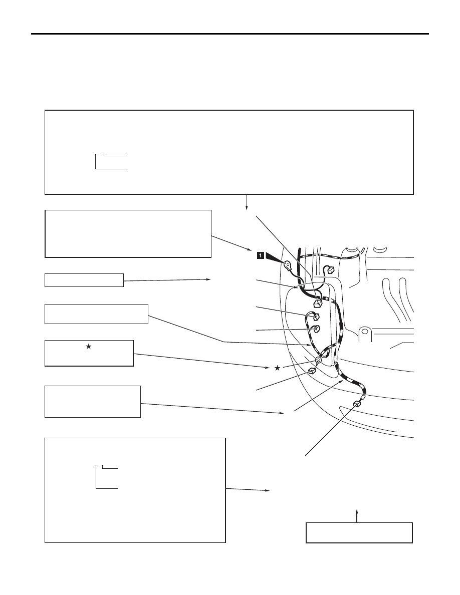
The wiring harness diagrams clearly show the con-
nector locations and harness configurations on 
actual vehicles. Some variations are included in one 

configuration diagram. Accordingly, some diagrams 
may not be applicable for individual vehicles.

ZC6005450000

Denotes connector No.
The same connector No. is used throughout the circuit diagrams to facilitate connector location searches.
The first alphabetical symbol indicates the location site of the connector and a number that follows is the unique number.
Numbers are usually assigned to parts in clockwise order on the diagram.

       Example: A-19


Number specific to connector (serial number)

   Connector 

location 

site 

symbol


A:  ENGINE COMPARTMENT 

D:  FLOOR AND ROOF


B:  ENGINE AND TRANSAXLE  

E:  DOOR


C:  DASH PANEL  


F:  LIFTGATE

Denotes ground point.
Same ground number is used throughout circuit
diagrams to facilitate search of ground point.
Refer to GROUP 70 COMPONENT LOCATIONS
-GROUND MOUNTING LOCATIONS for details
of ground points.

Denotes the color of the tube
(If not specified, it is black).
R:  Red
Y:   Yellow

The number of connector pins and the connector color
(except milk white)* are shown for ease of retrieval.

       Example: (2-B)


          Connector color


          (milk white if no color is indicated)


          Number of connector pins

*: Typical connector colors
        B:   Black 


BR: Brown

        Y:    Yellow   

V:    Violet

        L:    Blue 


O:   Orange

        G:   Green   

GR: Gray

        R:   Red 


NONE: Milk white

A-15 (2)              Fog light (RH)
A-16 (2-GR)       Horn (LOW)
A-17 (2-B)          Headlight (RH)
A-18 (2-B)          Windshield washer motor
A-19 (2-GR)       Dual pressure switch

Indicates the device to which the
connector is connected.

The mark            shows the
standard mounting position
of wiring harness.

A-17

A-16

A-15

A-18

A-19

Y

Denotes a section covered by a
corrugated tube.

Front wiring
harness (RH)

Denotes harness name.

ENGINE COMPARTMENT

CONFIGURATION DIAGRAMS

80A-4

ENGINE COMPARTMENT

Connector
symbol

A

Connector color
code
B : Black
BR : Brown
G : Green 
GR : Gray
L : Blue
None : Milk white
O : Orange
R : Red
V : Violet
Y : Yellow

A-01
A-02

A-03

A-04

Front wiring
harness

Grounding
cable

Fog light wiring
harness or
daytime running
light wiring
harness

A-45

A-50

A-51
A-52

A-53

A-54

A-55

A-56

A-57

A-58

A-59

A-60

1

A-01

(26-B)

ABS-ECU

A-02

(47-B)

ASC-ECU

A-03

(1-B)

Front wiring harness and theft-alarm 
horn sub wiring harness combination

A-04

(3-B)

Front height sensor <Headlight 
automatic leveling system>

A-05

(2-B)

Radiator fan motor

A-06

(2-B)

Hood switch

A-07

(4-GR)

Mass airflow sensor

A-08

(5-GR)

Windshield wiper motor

A-09

(2-B)

Brake fluid level switch

A-10

(2-B)

Side turn-signal light (LH)

A-11

(2-B)

Front wheel speed sensor (LH)

A-12

(24)

Front wiring harness and control 
wiring harness combination

A-13

(20)

Front wiring harness and control 
wiring harness combination

A-14X (4)

Fog light relay

A-15X (4)

Horn relay

A-16X (4)

A/C compressor clutch relay

A-17X (4)

Theft-alarm horn relay

A-18X (4)

A/T control relay

A-20X (4)

Headlight relay (High)

A-21X (4)

Throttle valve control servo relay

A-23X (4)

Daytime running light relay

A-24X (4)

Injector relay

A-27X (4)

Starter relay

A-28X (4)

Headlight relay (Low)

A-33X (4)

MFI relay

A-34X (4)

Radiator fan relay

A-35X (4)

Condenser fan relay

ENGINE COMPARTMENT

CONFIGURATION DIAGRAMS

80A-5

ZC6003230000

A-05

A-06

A-07

A-08

A-09

A-10

A-11

A-12

A-13

A-37

A-38

A-39

A-40

A-14X A-18X A-24X
A-15X A-20X A-27X
A-16X A-21X A-28X
A-17X A-23X A-33X

A-34X
A-35X
A-36X

A-41
A-42

A-43

A-44

A-49

A-48

A-46
A-47

12

15

4

A-36X (5)

Fan control relay

A-37

(12-B)

Headlight assembly (LH)

A-38

(2-B)

Headlight (High: LH)

A-39

(2-Y)

Front impact sensor (LH)

A-40

(4-GR)

Spare connector (for trailer harness)

A-41

(2-B)

Fog light (LH)

A-42

(2)

Daytime running light (LH)

A-43

(2-B)

Condenser fan motor

A-44

(2-B)

Ambient air temperature sensor

A-45

(1-B)

Horn (Low)

A-46

(2-B)

Front wiring harness and fog light 
wiring harness combination

A-47

(2-B)

Front wiring harness and daytime 
running light wiring harness 
combination

A-48

(2-B)

Radiator sensor

A-49

(1-B)

Horn (High)

A-50

(3-B)

A/C pressure sensor

A-51

(2-B)

Fog light (RH)

A-52

(2)

Daytime running light (RH)

A-53

(2-Y)

Front impact sensor (RH)

A-54

(2-B)

Washer motor

A-55

(2-B)

Headlight (High: RH)

A-56

(12-B)

Headlight assembly (RH)

A-57

(3-GR)

Front wiring harness and front height 
sensor sub wiring harness 
combination <Headlight automatic 
leveling system>

A-58

(1)

Theft-alarm horn

A-59

(2-B)

Front wheel speed sensor (RH)

A-60

(2-B)

Side turn-signal light (RH)

ENGINE AND TRANSAXLE

CONFIGURATION DIAGRAMS

80A-6

ENGINE AND TRANSAXLE

B-01

B-02

B-03

B-04

B-05

Connector
symbol

-01
thru
-21

B

B-15

B-16

B-17

B-18

B-19

B-20

B-21

Injector
wiring
harness

Control
wiring
harness

Connector color
code
B : Black
BR : Brown
G : Green 
GR : Gray
L : Blue
None : Milk white
O : Orange
R : Red
V : Violet
Y : Yellow

B-01

(3-B)

Ignition coil 1

B-02

(4-B)

Right bank heated oxygen sensor 
(Rear)

B-03

(4-GR)

Right bank heated oxygen sensor 
(Front)

B-04

(3-B)

Ignition coil 3

B-05

(3-B)

Ignition coil 5

B-06

(2-B)

Knock sensor 1

B-07

(2-B)

Evaporative emission purge solenoid

B-08

(6-B)

Throttle body assembly

B-09

(2-B)

Engine coolant temperature sensor

B-10

(64-GR) Engine control module

B-11

(48-GR) Engine control module

B-12

(6-GR)

Exhaust gas recirculation valve


Content   ..  65  66  67  68   ..