Mitsubishi Outlander XL. Manual - part 34
Vehicles with aluminum wheels
Standard value:
Camber 0°20' ± 0°30’ (Left/right deviation within 30’)
Caster 2°57' ± 0°30’ (Left/right deviation within 30’)
Kingpin inclination 12°44’ ± 1°30’
NOTE:
Camber and caster are preset at the factory and
cannot be adjusted.
Never subject the wheel bearings to the vehicle load when
the drive shaft nuts are loosened.
ZB600967AA00
MB991004
160 ± 16 N·m
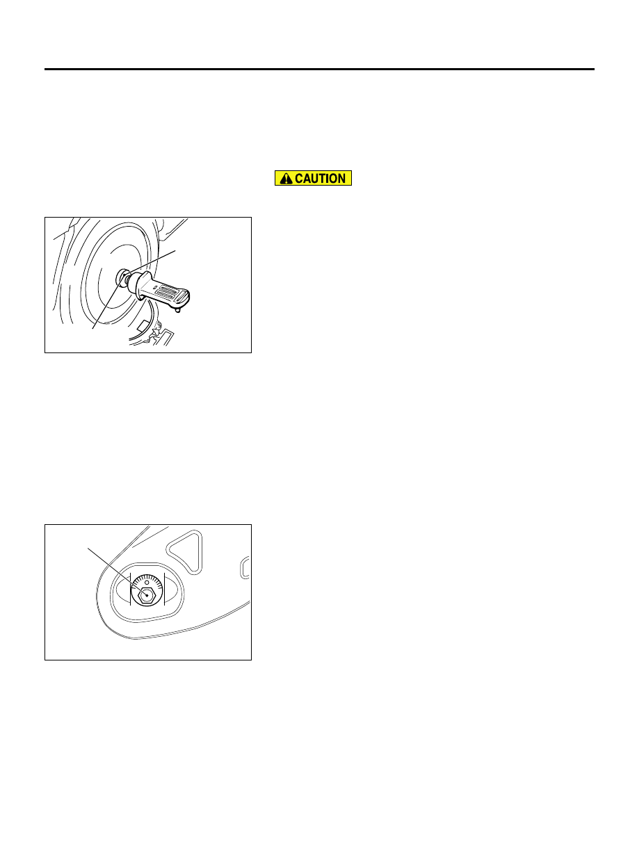
NOTE:
For vehicles with aluminum type wheels, attach the
camber/caster/kingpin gauge to the driveshaft by using the
special tool MB991004. Tighten the special tool MB991004 to
the same torque 245 ± 29 N·m (181 ± 21 ft-lb) as the
driveshaft nut.
REAR WHEEL ALIGNMENT CHECK AND
ADJUSTMENT
M40800000100USA0000010000
1.
Before the wheel alignment measurement, adjust the rear
suspension, wheel, and tires in good condition.
2.
Park the vehicle on a level surface to measure the wheel
alignment.
TOE-IN
Standard value: 3 ± 2 mm (0.12 ± 0.08 inch)
If it is out of the standard range, adjust as follows:
ZB6006980000
Toe adjusting bolt
Turn the toe adjusting bolt (the mounting bolt inside the body on
the control link) to adjust.
Left wheels: Clockwise → (+) Toe in
Right wheels: Clockwise → (-) Toe in
Toe-in varies approximately 2.6 mm (0.10inch) (equivalent to 0°
16' of the toe angle for one side) for each scale mark.
CAMBER
Standard value: -0°25' ±0°30' (left/right difference 0°30'
max)
REFERENCE MATERIAL
8-11
ADJUSTMENT OF OTHER PARTS