Mitsubishi Outlander GS45X. Manual - part 992
THROTTLE BODY ASSEMBLY
TSB Revision
MULTIPORT FUEL INJECTION (MFI) <3.0L ENGINE>
13B-901
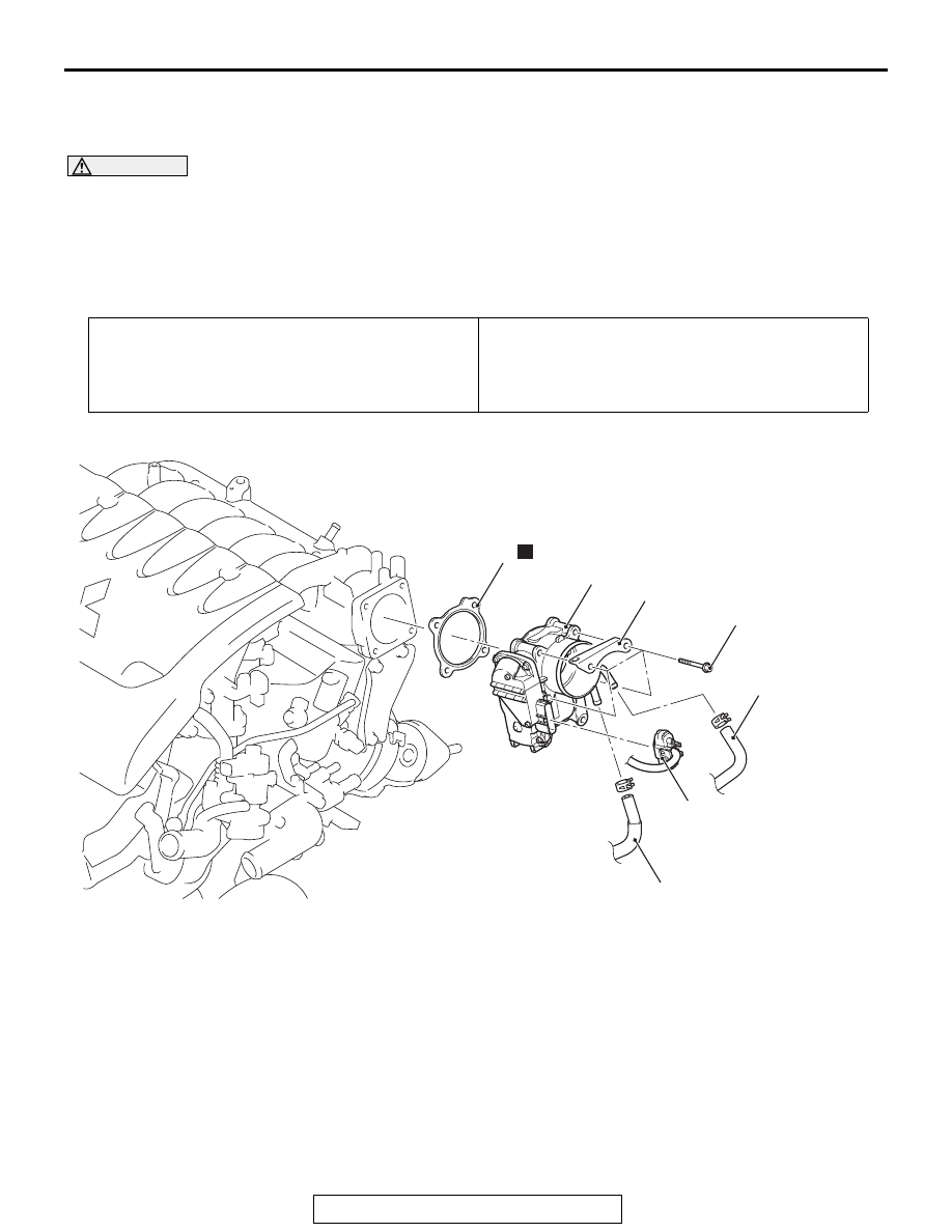
THROTTLE BODY ASSEMBLY
REMOVAL AND INSTALLATION
M1131007702948
CAUTION
• When the throttle body assembly replacement is performed, use scan tool MB991958 to initialize
the learning value (Refer to GROUP 00, Precautions Before Service
− Initialization Procedure for
Learning Value in MFI Engine
• Never loosen the screw fixing the throttle body assembly resin cover. If the screw is loosened, the
sensor incorporated in the resin cover is misaligned and the throttle body assembly does not
work normally.
Pre-removal Operation
• Engine Coolant Draining (Refer to GROUP 14, On-vehicle
Service
− Engine Coolant Replacement
• Air Intake Hose Removal (Refer to GROUP 15, Air
Cleaner <3.0L Engine>
Post-installation Operation
• Air Intake Hose Installation (Refer to GROUP 15, Air
Cleaner <3.0L Engine>
• Engine Coolant Refilling (Refer to GROUP 14, On-vehicle
Service
− Engine Coolant Replacement
AC809028
1
3
2
5
6
N
AB
23 ± 6 N·m
17 ± 4 ft-lb
4
Removal steps
>>
B
<<
•
Initialization procedure (Installation
only)
1.
Throttle body assembly connector
connection
2.
Water hose connection
3.
Water hose connection
4.
Harness bracket
5.
Throttle body assembly
>>
A
6.
Throttle body gasket
Removal steps (Continued)