Mitsubishi Outlander GS45X. Manual - part 990


  Index      Mitsubishi     Mitsubishi Outlander GS45X - service repair manual


Search            


Content   ..  988  989  990  991   ..


Mitsubishi Outlander GS45X. Manual - part 990


ON-VEHICLE SERVICE

TSB Revision

MULTIPORT FUEL INJECTION (MFI) <3.0L ENGINE>

13B-893

NOTE: For removal and installation of the heated oxygen 
sensor, refer to GROUP 15, Exhaust Manifold 

 Removal 

and Installation 

P.15-18

.

.

Left bank heated oxygen sensor (rear)

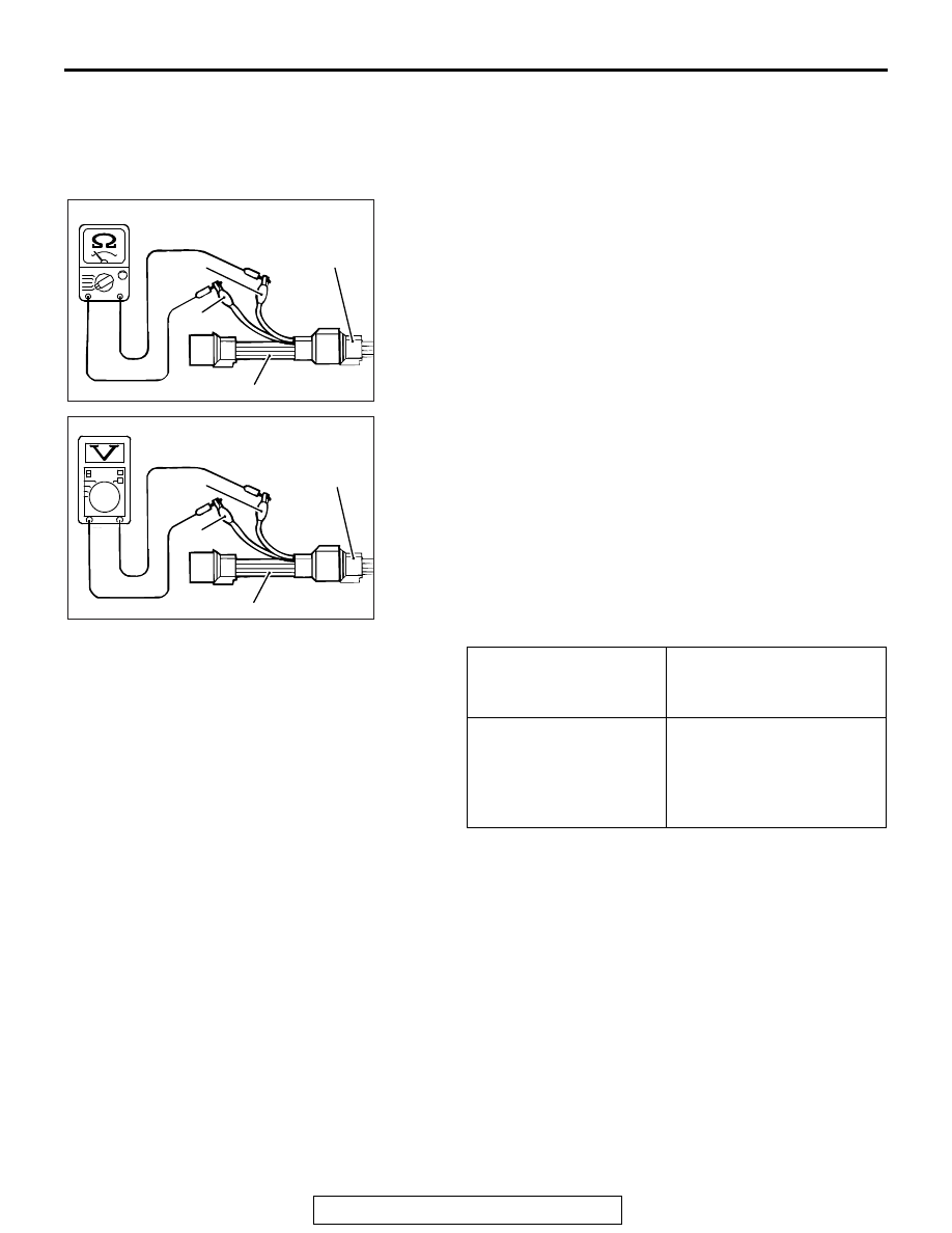
1. Disconnect the heated oxygen sensor connector and 

connect special tool MB991316 to the connector on the 
heated oxygen sensor side.

2. Measure the resistance between terminal No. 1 (red clip) 

and terminal No. 3 (blue clip) on the heated oxygen sensor 
connector.

Standard value: 11 

 18 Ω [at 20 °C (68 °F)]

3. If the resistance deviates from standard value, replace the 

heated oxygen sensor.

4. Warm up the engine until engine coolant is 80

°C (176°F) or 

higher.

5. Drive at 50 km/h (31 mph) or more for 10 minutes.
6. Connect a digital voltage meter between terminal No. 2 

(black clip) and terminal No. 4 (white clip).

7. Measure the output voltage of the heated oxygen sensor 

under the following driving.

• Transaxle: 2 nd

• Drive with wide open throttle

• Engine: 3,500 r/min or more

Standard value:

NOTE: If the temperature of sensing area does not reach 
the high temperature [of approximately 400

°

C (752

°

F) or 

more] even though the oxygen sensor is normal, the output 
voltage would be possibly low in spite of the rich air-fuel 
ratio.
NOTE: When the vehicle is driven with high loads, the tem-
perature of the sensing area of the heated oxygen sensor is 
sufficiently high. Thus, it is not necessary to apply the volt-
age to the heater.

8. If the output voltage is not within the standard value, replace 

the heated oxygen sensor.
NOTE: For removal and installation of the heated oxygen 
sensor, refer to GROUP 15, Exhaust Manifold 

 Removal 

and Installation 

P.15-18

.

HEATED OXYGEN 
SENSOR OUTPUT 
VOLTAGE

REMARKS

0.6 

− 1.0 V

High load operation makes 
air/fuel ratio richer and 
normal heated oxygen 
sensor also can output 
voltage of 0.6 

− 1.0 V.

AK7000101AB

MB991316

Blue

Red

Heated oxygen
sensor component
side connector

AK700102

MB991316

White

Black

AB

Heated oxygen
sensor component
side connector

ON-VEHICLE SERVICE

TSB Revision

MULTIPORT FUEL INJECTION (MFI) <3.0L ENGINE>

13B-894

INJECTOR CHECK

M1131005202635

.

Right bank side (number 1, 3, 5 cylinders)

1. Disconnect the intermediate connector B-21.

2. Measure the resistance between the injector intermediate 

connector terminals.

Standard value:

3. Connect the injector intermediate connector.

.

Left bank side (number 2, 4, 6 cylinders)

1. Disconnect the injector connector.
2. Measure the resistance between injector side connector 

terminals 1 and 2.

Standard value: 10.5 

 13.5 Ω [at 20°C (68°F)]

3. Connect the injector connector.

THROTTLE ACTUATOR CONTROL MOTOR 
CHECK

M1131051000649

.

<Operation Inspection>

WARNING

When checking the throttle valve operation, never 
insert fingers into the throttle valve. The extremely 
strong power of the throttle valve motor might trap 
and injure fingers.

1. Disconnect the air intake hose from the throttle body.

INJECTOR 
No.

MEASUREM
ENT 
TERMINAL

RESISTANCE

No. 1

− 7

10.5 

− 13.5 Ω [20°C 

(68

°F)]

No. 3

− 8

No. 5

− 9

AK900134

AE

B-21

Intermediate
connector

1

2 3

6

7 8

4 5

9 10

AK700107

B-21 
Intermediate connector

AB

AK700108

1 2

Injector
connector

AB

ON-VEHICLE SERVICE

TSB Revision

MULTIPORT FUEL INJECTION (MFI) <3.0L ENGINE>

13B-895

2. Set the ignition switch to the "ON" position.
3. Operate the accelerator pedal and confirm that the throttle 

valve is opening and closing accordingly.

.

<Checking the Terminal Resistance>

WARNING

When touching the throttle valve, surely shut off the 
driving circuits of the throttle valve. In the event that 
the throttle valve is operated, a finger might be 
injured as the result of being caught by the throttle 
valve.

1. Disconnect the throttle position sensor connector.
2. Measure the resistance between terminal No. 1 and No. 2.

Standard value: 0.3 

 80 Ω [at 20°C (68°F)]

3. If resistance is outside the standard value, replace the 

throttle body assembly.

ENGINE OIL CONTROL VALVE CHECK

M1131053200456

Required Special Tools

• MB991658: Test Harness

.

Checking the Operation Sound

1. Disconnect the engine oil control valve connector.

CAUTION

To prevent the coil from burning, keep the duration of the 
voltage application as short as possible.
2. Check that the operation sound of the engine oil control 

valve can be heard when the positive battery voltage is 
supplied to the engine oil control valve. (Use the special tool 
MB991658 to connect terminal No. 1 of the engine oil control 
valve connector to the positive battery terminal and terminal 
No. 2 to the negative battery terminal.)

3. If the operation sound cannot be heard, replace the engine 

oil control valve.

.

Checking the Coil Resistance

1. Disconnect the engine oil control valve connector.

6

1 2 3 4 5

AK700528 AB

Throttle actuator control
motor connector

AK700109 AB

Engine oil 
control 
valve

MB991658

ON-VEHICLE SERVICE

TSB Revision

MULTIPORT FUEL INJECTION (MFI) <3.0L ENGINE>

13B-896

2. Measure resistance between terminal No. 1 and terminal 

No. 2 of the connector at the engine oil control valve side.

Standard value: 6.9 

 7.9 Ω [at 20°C (68°F)]

3. If resistance is not within the standard value, replace the 

engine oil control valve.

EVAPORATIVE EMISSION PURGE SOLENOID 
CHECK

M1131005600455

Refer to GROUP 17, Emission Control System 

− Evaporative 

Emission System 

− Evaporative Emission Purge Solenoid 

Check 

P.17-78

.

EVAPORATIVE EMISSION VENTILATION 
SOLENOID CHECK

M1131012800387

Refer to GROUP 17, Emission Control 

− Evaporative Emission 

Canister and Fuel Tank Pressure Relief Valve 

− Inspection 

P.17-88

.

EGR VALVE CHECK

M1131051500150

Refer to GROUP 17, Emission Control 

− Exhaust Gas Recircu-

lation (EGR) System 

− EGR Valve Check 

P.17-81

.

AK700110

1 2

AB

Harness connector:
component side


Content   ..  988  989  990  991   ..