Mitsubishi Outlander GS45X. Manual - part 970


  Index      Mitsubishi     Mitsubishi Outlander GS45X - service repair manual


Search            


Content   ..  968  969  970  971   ..


Mitsubishi Outlander GS45X. Manual - part 970


MULTIPORT FUEL INJECTION (MFI) DIAGNOSIS

TSB Revision

MULTIPORT FUEL INJECTION (MFI) <3.0L ENGINE>

13B-813

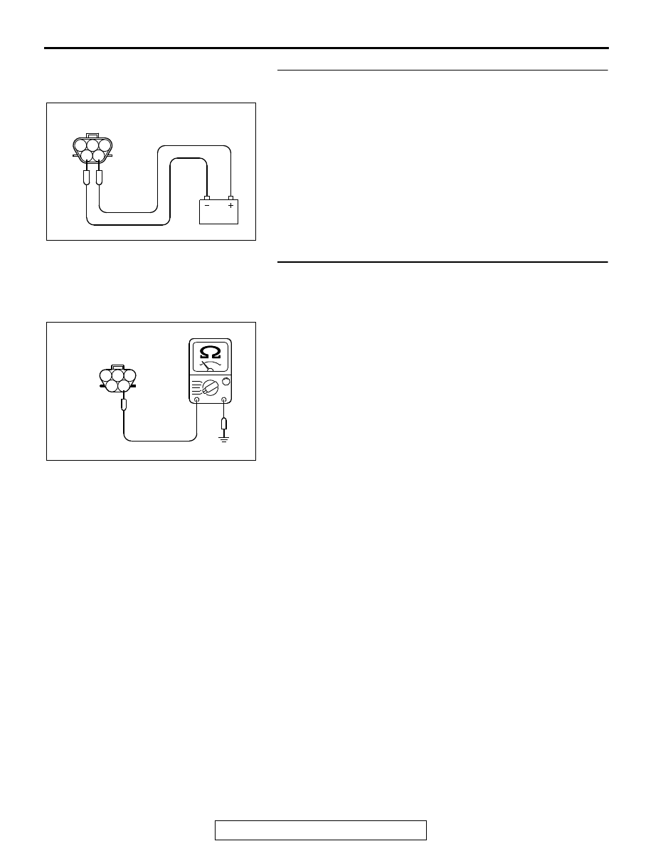
STEP 5. Check the fuel pump operation.
(1) Disconnect fuel pump connector D-20.
(2) Use jumper wires to connect fuel pump connector terminal 

No. 5 to the positive battery terminal and terminal No. 4 to 
the negative battery terminal.

• An operating sound of the fuel pump should be heard.

Q: Is the fuel pump operating properly?

YES : Go to Step 6.
NO :  Replace the fuel pump. Then confirm that the 

malfunction symptom is eliminated.

STEP 6. Check for continuity at fuel pump harness side 
connector D-20.
(1) Disconnect the connector D-20 and measure at the harness 

side.

(2) Check for the continuity between terminal No. 4 and 

ground.

• Should be less than 2 ohms.

Q: Does continuity exist?

YES : Go to Step 7.
NO :  Repair harness wire between fuel pump connector 

D-20 (terminal No. 4) and ground because of open 
circuit or harness damage. Then confirm that the 
malfunction symptom is eliminated.

AK700217

1 2 3

4 5

AB

Fuel pump side
connector

AK700218

1

2

3

4

5

AB

D-20 harness connector:
component side 

MULTIPORT FUEL INJECTION (MFI) DIAGNOSIS

TSB Revision

MULTIPORT FUEL INJECTION (MFI) <3.0L ENGINE>

13B-814

STEP 7. Check for open circuit and short circuit to ground 
and harness damage between ETACS-ECU connector 
C-314 (terminal No. 1) and fuel pump connector D-20 
(terminal No. 5).
(1) Disconnect the connector C-314 and D-20 measure at the 

harness side.

(2) Measure the resistance between connector C-314 (terminal 

No. 1) and connector D-20 (terminal No. 5).

• Should be less than 2 ohms.

(3) Check for the continuity between connector D-20 (terminal 

No. 5) and ground.

• Not continuity.

Q: Is the harness wire in good condition?

YES : Go to Step 8.
NO :  Repair it. Then confirm that the malfunction symptom 

is eliminated.

STEP 8. Check connector B-11 at ECM for damage.
Q: Is the connector in good condition?

YES : Go to Step 9.
NO :  Repair or replace it. Refer to GROUP 00E, Harness 

Connector Inspection 

P.00E-2

. Then confirm that the 

malfunction symptom is eliminated.

AK700219

1

2

3

4

5

1

2

AB

C-314 harness
connector:
component side 

D-20 harness connector:
component side 

AK700220

1

2

3

4

5

AB

D-20 harness connector:
component side 

MULTIPORT FUEL INJECTION (MFI) DIAGNOSIS

TSB Revision

MULTIPORT FUEL INJECTION (MFI) <3.0L ENGINE>

13B-815

STEP 9. Measure the power supply voltage at ECM 
connector B-11.
(1) Disconnect the connector B-11 and measure at the harness 

side.

(2) Turn the ignition switch to the "ON" position.
(3) Measure the voltage between terminal No. 96 and ground.

• Voltage should be battery positive voltage.

(4) Turn the ignition switch to the "LOCK" (OFF) position.
Q: Is battery positive voltage (approximately 12 volts) 

present?
YES : 
Replace the ECM. When the ECM is replaced, 

register the ID code. Refer to GROUP 42B, Diagnosis 
− ID Codes Registration Judgment Table <Vehicles 

with KOS> 

P.42B-15

 or GROUP 42C, Diagnosis 

− ID 

Codes Registration Judgment Table <Vehicles with 
WCM> 

P.42C-10

.

NO :  Repair harness wire between ETACS-ECU connector 

C-304 (terminal No. 11) and ECM connector B-11 
(terminal No. 96) because of open circuit. Then 
confirm that the malfunction symptom is eliminated.

AK700221

71 72 73 74 75 76 77 78 79 80 81 82

83 84 85 86 87 88 89 90 91 92 93 94

95 96 97 98 99

100 101 102 103 104

112 113 114

109

108

107

110 111

115 116

106

105

118

117

82 81 80 79 78 77 76 75 74 73 72 71

94 93 92 91 90 89 88 87 86 85 84 83

99 98 97 96 95

100

101

102

103

104

105

106

112

113

114

109 108

107

110

111

115

116

117

118

AB

B-11 harness
connector:
component side 

MULTIPORT FUEL INJECTION (MFI) DIAGNOSIS

TSB Revision

MULTIPORT FUEL INJECTION (MFI) <3.0L ENGINE>

13B-816

INSPECTION PROCEDURE 23: Ignition Switch-ST System and Transmission Range Switch System

M

1

1

1

2

3
4

5 6

1 2 3 4

7

8

9 10

71 72 73 74 75 76 77 78 79 80 81 82

83 84 85 86 87 88 89 90 91 92 93 94

95 96 97 98 99

100 101 102 103 104

112 113 114

109

108

107

110 111

115 116

106

105

118

117

7

3

8

1

4

9

13 14

16

15

10 11 12

17 18 19

2

5 6

1

6

4

5

9

8

10 11

13

15

14

12

16

7

2 3

1 2 3
4 5 6

AK900385

1

10 111213 14 1516 17 1819 20

2 3 4

5 6 7 8 9

1

2

3 4 5 6 7 8 9 10 11 12 13 14 15 16

17 18 19 20 21 22 23 24 25 26 27 28 29 30 31 32

33 34 35 36 37 38 39 40 41 42 43 44 45 46 47 48

49 50 51 52 53 54 55 56 57 58 59 60 61 62 63 64

D

Ds

N

R

P

OFF

ON

1

OFF

ON

10

106

6

B-11

105

15

7

C-304

ENGINE
CONTROL
MODULE

A-13

B-10

ETACS-ECU

7

IG2

ST

LOCK

ACC

IG1

5

B-114 

(MU801211)

B-110

MU802355

STARTER

STARTER
RELAY

TRANSMISSION
RANGE
SWITCH

B-113

A-27X

6

3

1

4

2

BLA

CK-RED

RED-WHITE

RED-WHITE

WHITE

GREEN

GREEN

ORANGE

LIGHT

GREEN

12

11

C-315 

MU801890

C-210

IGNITION SWITCH

STARTING SYSTEM CIRCUIT

AB

BATTERY

FUSIBLE LINK 24

1

BLA

CK

BLA

CK

BLA

CK

BLA

CK-RED

BLUE-BLA

CK

BLUE-BLA

CK

BLA

CK-RED


Content   ..  968  969  970  971   ..