Mitsubishi Outlander GS45X. Manual - part 971
MULTIPORT FUEL INJECTION (MFI) DIAGNOSIS
TSB Revision
MULTIPORT FUEL INJECTION (MFI) <3.0L ENGINE>
13B-817
.
AK900601
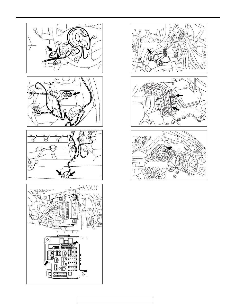
Connector: C-210
C-210
AB
AK900602
Connector: A-13
A-13
AB
AK900153
B-114 (B)
B-113
Connectors: B-113, B-114
AD
AK700445AB
ETACS-ECU
C-315
Connectors: C-304, C-315
C-304
AK602925
Connector: B-110
B-110 (B)
AE
AK700430AB
ECM
B-11 (GR)
B-10 (GR)
Connectors: B-10, B-11
AK700438AB
Starter relay
A-27X
Connector: A-27X