Mitsubishi Outlander GS45X. Manual - part 968


  Index      Mitsubishi     Mitsubishi Outlander GS45X - service repair manual


Search            


Content   ..  966  967  968  969   ..


Mitsubishi Outlander GS45X. Manual - part 968


MULTIPORT FUEL INJECTION (MFI) DIAGNOSIS

TSB Revision

MULTIPORT FUEL INJECTION (MFI) <3.0L ENGINE>

13B-805

.

CIRCUIT OPERATION

• Battery positive voltage is applied to the MFI 

relay (terminals No. 3, No. 4).

• When the ignition switch is turned to the "ON" 

position, battery positive voltage is applied to the 
ECM (terminal No. 92). When battery positive 
voltage is applied, the ECM turns the power tran-
sistor in the ECM "ON" and grounds the MFI relay 
coil. With this, the MFI relay turns "ON" the bat-
tery positive voltage is supplied to the ECM (ter-
minals No. 82) from the MFI relay (terminal No. 
2).

• A battery positive voltage is constantly supplied 

to the ECM (terminal No. 104) as the backup 
power.

• The ECM (terminals No. 81, No. 93) is grounded 

to the vehicle body.

.

COMMENT

• When the ignition switch "ON" signal is input into 

the ECM via ETACS-ECU, the ECM turns "ON" 
the MFI relay. This causes battery positive volt-
age to be supplied to the ECM, sensor and actua-
tor.

.

TROUBLESHOOTING HINTS (The most 
likely causes for this code to be set are:) 

• Malfunction of the ignition switch.

• Malfunction of the MFI relay.

• Improper connector contact, open circuit or 

short-circuit harness wire.

• Malfunction of the ECM.
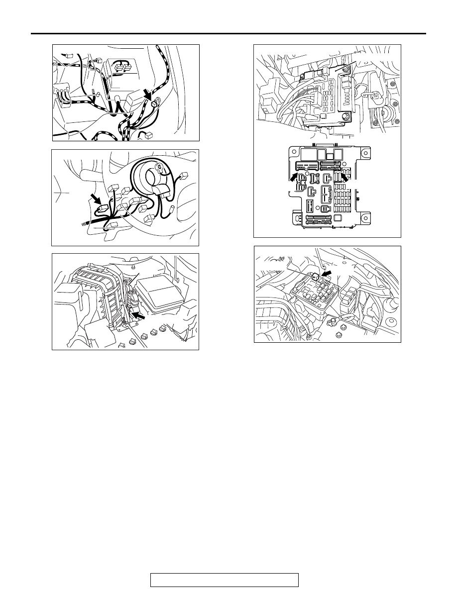
AKA00835

Connector: A-66

A-66 (GR)

AB

AK900601

Connector: C-210

C-210

AB

AK700402AB

ECM

B-11 (GR)

Connector: B-11

AK700414 AB

ETACS-ECU

C-317

Connectors: C-304, C-317

C-304

AK700399AB

MFI relay

A-33X

Connector: A-33X

MULTIPORT FUEL INJECTION (MFI) DIAGNOSIS

TSB Revision

MULTIPORT FUEL INJECTION (MFI) <3.0L ENGINE>

13B-806

DIAGNOSIS

STEP 1. Check harness connector A-33X at MFI relay and 
harness connector B-11 at ECM for damage.
Q: Is the connector in good condition?

YES : Go to Step 2.
NO :  Repair or replace it. Refer to GROUP 00E, Harness 

Connector Inspection 

P.00E-2

. Then confirm that the 

malfunction symptom is eliminated.

STEP 2. Check the MFI relay.
(1) Remove the MFI relay.
(2) Check for continuity between the MFI relay terminals No. 1 

and No. 3.

• There should be continuity.

(3) Use jumper wires to connect MFI relay terminal No. 3 to the 

positive battery terminal and terminal No. 1 to the negative 
battery terminal.

(4) Check for continuity between the MFI relay terminals No. 2 

and No. 4 while connecting and disconnecting the jumper 
wire at the negative battery terminal.

• Should be less than 2 ohms. (Negative battery terminal 

connected)

• Should be open loop. (Negative battery terminal discon-

nected)

(5)  Install the MFI relay.
Q: Is the measured resistance within the specified range?

YES : Go to Step 3.
NO :  Replace the MFI relay. Then confirm that the 

malfunction symptom is eliminated.

AK703903

1

3

2

4

AB

MFI relay side
connector

1

3

2

4

AK703904AB

MFI
relay side
connector 

MULTIPORT FUEL INJECTION (MFI) DIAGNOSIS

TSB Revision

MULTIPORT FUEL INJECTION (MFI) <3.0L ENGINE>

13B-807

STEP 3. Measure the power supply voltage at MFI relay 
harness side connector A-33X.
(1) Disconnect the connector A-33X and measure at the 

harness side.

(2) Measure the voltage between terminals No. 3, No. 4 and 

ground.

• Voltage should be battery positive voltage.

Q: Is battery positive voltage (approximately 12 volts) 

present?
YES : 
Go to Step 4.
NO :  Repair harness wire between fusible link (36) and MFI 

relay connector A-33X (terminal No. 3, No. 4) 
because of open circuit. Then confirm that the 
malfunction symptom is eliminated.

STEP 4. Measure the ignition switch-IG signal voltage at 
ECM harness side connector B-11.
(1) Disconnect the connector B-11 and measure at the harness 

side.

(2) Turn the ignition switch to the "ON" position.
(3) Measure the voltage between terminal No. 92 and ground.

• Voltage should be battery positive voltage.

(4) Turn the ignition switch to the "LOCK" (OFF) position.
Q: Is battery positive voltage (approximately 12 volts) 

present?
YES : 
Go to Step 5.
NO :  Check harness connectors C-304 and C-317 at 

intermediate connector for damage, and repair or 
replace as required. Refer to, GROUP 00E, Harness 
Connector Inspection 

P.00E-2

. If intermediate 

connectors are in good condition, repair harness wire 
between ignition switch connector C-210 (terminal 
No. 2) and ECM connector B-11 (terminal No. 92) 
because of open circuit. Then confirm that the 
malfunction symptom is eliminated.

AK704114

3

1

2

4

AB

A-33X harness
connector:
component side

82 81 80 79 78 77 76 75 74 73 72 71

94 93 92 91 90 89 88 87 86 85 84 83

99 98 97 96 95

100

101

102

103

104

105

106

112

113

114

109 108

107

110

111

115

116

117

118

AK700211AB

B-11 harness
connector:
component side

MULTIPORT FUEL INJECTION (MFI) DIAGNOSIS

TSB Revision

MULTIPORT FUEL INJECTION (MFI) <3.0L ENGINE>

13B-808

STEP 5. Measure the backup power supply voltage at ECM 
harness side connector B-11.
(1) Disconnect the connector B-11 and measure at the harness 

side.

(2) Measure the voltage between terminal No. 104 and ground.

• Voltage should be battery positive voltage.

Q: Is battery positive voltage (approximately 12 volts) 

present?
YES : 
Go to Step 6.
NO :  Repair harness wire between relay box (fuse 2) and 

ECM connector B-11 (terminal No. 104) because of 
short circuit. Then confirm that the malfunction 
symptom is eliminated.

STEP 6. Check for continuity at ECM harness side 
connector B-11.
(1) Disconnect the connector B-11 and measure at the harness 

side.

(2) Check for the continuity between terminals (No. 81, No. 93) 

and ground.

• Should be less than 2 ohms.

Q: Does continuity exist?

YES : Go to Step 7.
NO :  Check harness connector A-66 at intermediate 

connector for damage, and repair or replace as 
required. Refer to GROUP 00E, Harness Connector 
Inspection 

P.00E-2

. If intermediate connector is in 

good condition, repair harness wire between ECM 
connector B-11 (terminal No. 81, No. 93) and ground 
because of open circuit and harness damage. Then 
confirm that the malfunction symptom is eliminated.

AK700212

82 81 80 79 78 77 76 75 74 73 72 71

94 93 92 91 90 89 88 87 86 85 84 83

99 98 97 96 95

100

101

102

103

104

105

106

112

113

114

109 108

107

110

111

115

116

117

118

AB

Special tool 48-pin 
connector:
component side 

82 81 80 79 78 77 76 75 74 73 72 71

94 93 92 91 90 89 88 87 86 85 84 83

99 98 97 96 95

100

101

102

103

104

105

106

112

113

114

109 108

107

110

111

115

116

117

118

AK703905 AB

B-11 harness
connector:
component side 


Content   ..  966  967  968  969   ..