Mitsubishi Outlander GS45X. Manual - part 948
MULTIPORT FUEL INJECTION (MFI) DIAGNOSIS
TSB Revision
MULTIPORT FUEL INJECTION (MFI) <3.0L ENGINE>
13B-725
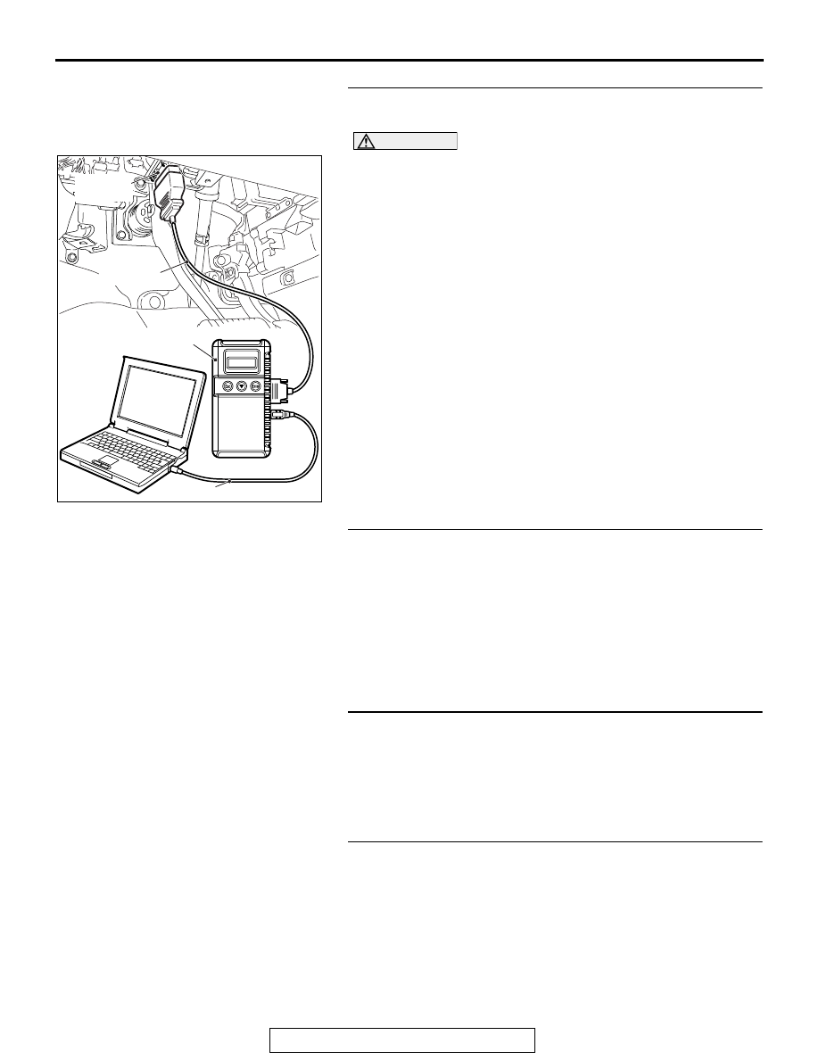
STEP 1. Using scan tool MB991958, diagnose CAN bus
line.
CAUTION
To prevent damage to scan tool MB991958, always turn the
ignition switch to the "LOCK" (OFF) position before con-
necting or disconnecting scan tool MB991958.
(1) Connect scan tool MB991958 to the data link connector.
(2) Turn the ignition switch to the "ON" position.
(3) Diagnose CAN bus line.
(4) Turn the ignition switch to the "LOCK" (OFF) position.
Q: Is the CAN bus line normal?
YES : Go to Step 2.
NO : Repair the CAN bus line. Refer to GROUP 54C,
Diagnosis
− CAN Bus Diagnostics Table
Then go to Step 7.
STEP 2. Using scan tool MB991958, read the diagnostic
trouble code (DTC).
(1) Turn the ignition switch to the "ON" position.
(2) Read the ETACS-DTC.
(3) Turn the ignition switch to the "LOCK" (OFF) position.
Q: Is the ETACS-DTC set?
YES : Refer to GROUP 54A, ETACS
− Diagnostic Trouble
.
NO : Go to Step 3.
STEP 3. Check harness connector B-11 at ECM for
damage.
Q: Is the harness connector in good condition?
YES : Go to Step 4.
NO : Repair or replace it. Refer to GROUP 00E, Harness
Connector Inspection
. Then to go to Step 7.
STEP 4. Check for short circuit to power supply between
ETACS-ECU connector C-304 (terminal No. 10) and ECM
connector B-11 (terminal No. 92).
Q: Is the harness wire in good condition?
YES : Go to Step 5.
NO : Repair it. Then to go to Step 7.
AK700568AB
MB991824
MB991827
MB991910
Data link
connector