Mitsubishi Outlander GS45X. Manual - part 949
MULTIPORT FUEL INJECTION (MFI) DIAGNOSIS
TSB Revision
MULTIPORT FUEL INJECTION (MFI) <3.0L ENGINE>
13B-729
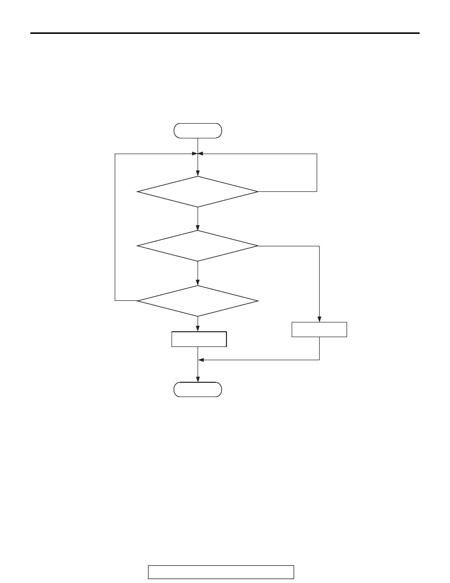
DTC SET CONDITIONS
Logic Flow Chart
Check Conditions
• Battery positive voltage is between 10 and 16.5
volts.
Judgement Criterion
• Unable to receive TCM signals through the CAN
bus line 4 seconds.
.
OBD-II DRIVE CYCLE PATTERN
None.
.
TROUBLESHOOTING HINTS (The most
likely causes for this code to be set are:)
• CAN line harness damage or connector damage.
DIAGNOSIS
Required Special Tools:
• MB991958: Scan tool (M.U.T.-III Sub Assembly)
• MB991824: V.C.I.
• MB991827: USB Cable
• MB991910: Main Harness A
AK604369
Start
Yes
Yes
Yes
No
No
No
Continuous failure
for specified time
Malfunction
End
Good
Monitoring
conditions
Communication status
fails