Mitsubishi Outlander GS45X. Manual - part 946


  Index      Mitsubishi     Mitsubishi Outlander GS45X - service repair manual


Search            


Content   ..  944  945  946  947   ..


Mitsubishi Outlander GS45X. Manual - part 946


MULTIPORT FUEL INJECTION (MFI) DIAGNOSIS

TSB Revision

MULTIPORT FUEL INJECTION (MFI) <3.0L ENGINE>

13B-717

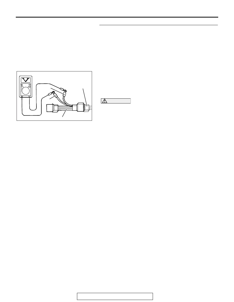
STEP 3. Check the left bank heated oxygen sensor (front).
(1) Disconnect the left bank heated oxygen sensor (front) 

connector B-14 and connect test harness special tool 
MD998464 to the connector on the left bank heated oxygen 
sensor (front) side.

(2) Warm up the engine until engine coolant temperature 

reaches 80

°C (176°F) or higher.

(3) Rev the engine for 5 minutes or more with the engine speed 

of 2,000 r/min.

(4) Connect a digital voltage meter between terminal No. 2 

(black clip) and terminal No. 4 (white clip).

(5) While repeatedly revving the engine, measure the left bank 

heated oxygen sensor (front) output voltage.

Standard value: 0.6 

 1.0 V

CAUTION

• Be very careful when connecting the jumper wires; 

incorrect connection can damage the heated oxygen 
sensor.

• Be careful the heater can be damaged if a voltage 

beyond 8 volts is applied to the heated oxygen sensor 
heater.
NOTE: If the temperature of sensing area does not reach 
the high temperature [of approximately 400

°

C (752

°

F) or 

more] even though the heated oxygen sensor is normal, the 
output voltage would be possibly low in spite of the rich air/ 
fuel ratio. Therefore, if the output voltage is low, use a 
jumper wire to connect the terminal No. 1 (red clip) and the 
terminal No. 3 (blue clip) of the heated oxygen sensor with 
the positive terminal and the negative terminal of 8 volts 
power supply respectively, then check again.

Q: Is the measured voltage between 0.6 and 1.0 volt?

YES : Go to Step 4.
NO :  Replace the left bank heated oxygen sensor (front). 

Then go to Step 19.

AK700104

MD998464

White

Black

AB

Heated oxygen
sensor component
side connector

MULTIPORT FUEL INJECTION (MFI) DIAGNOSIS

TSB Revision

MULTIPORT FUEL INJECTION (MFI) <3.0L ENGINE>

13B-718

STEP 4. Check the right bank heated oxygen sensor (rear).
(1) Disconnect the right bank heated oxygen sensor (rear) 

connector B-02 and connect test harness special tool 
MD998464 to the connector on the right bank heated 
oxygen sensor (rear) side.

(2) Warm up the engine until engine coolant temperature 

reaches 80

°C (176°F) or higher.

(3) Drive at 50 km/h (31 mph) or more for 10 minutes.
(4) Connect a digital voltage meter between terminal No. 2 

(black clip) and terminal No. 4 (white clip).

(5) Measure the output voltage of heated oxygen sensor under 

the following driving.

• Transaxle: 2nd speed

• Drive with wide open throttle

• Engine: 3,500 r/min or more

Standard value: 0.6 

 1.0 V

NOTE: If the temperature of sensing area does not reach 
the high temperature [of approximately 400

°

C (752

°

F) or 

more] even though the heated oxygen sensor is normal, the 
output voltage would be possibly low in spite of the rich 
air-fuel ratio.
NOTE: When the vehicle is driven with high loads, the tem-
perature of the sensing area of the heated oxygen sensor is 
sufficiently high. Thus, it is not necessary to apply the volt-
age to the heater.

Q: Is the measured voltage between 0.6 and 1.0 volt?

YES : Go to Step 5.
NO :  Replace the right bank heated oxygen sensor (rear). 

Then go to Step 19.

STEP 5. Check the left bank heated oxygen sensor (rear).
(1) Disconnect the left bank heated oxygen sensor (rear) 

connector B-13 and connect test harness special tool 
MB991316 to the connector on the left bank heated oxygen 
sensor (rear) side.

(2) Warm up the engine until engine coolant temperature 

reaches 80

°C (176°F) or higher.

(3) Drive at 50 km/h (31 mph) or more for 10 minutes.
(4) Connect a digital voltage meter between terminal No. 2 

(black clip) and terminal No. 4 (white clip).

(5) Measure the output voltage of heated oxygen sensor under 

the following driving.

• Transaxle: 2nd speed

• Drive with wide open throttle

• Engine: 3,500 r/min or more

Standard value: 0.6 

 1.0 V

NOTE: If the temperature of sensing area does not reach 
the high temperature [of approximately 400

°

C (752

°

F) or 

more] even though the heated oxygen sensor is normal, the 
output voltage would be possibly low in spite of the rich 
air-fuel ratio.

AK700104

MD998464

White

Black

AB

Heated oxygen
sensor component
side connector

AK700102

MB991316

White

Black

AB

Heated oxygen
sensor component
side connector

MULTIPORT FUEL INJECTION (MFI) DIAGNOSIS

TSB Revision

MULTIPORT FUEL INJECTION (MFI) <3.0L ENGINE>

13B-719

NOTE: When the vehicle is driven with high loads, the tem-
perature of the sensing area of the heated oxygen sensor is 
sufficiently high. Thus, it is not necessary to apply the volt-
age to the heater.

Q: Is the measured voltage between 0.6 and 1.0 volt?

YES : Go to Step 6.
NO :  Replace the left bank heated oxygen sensor (rear). 

Then go to Step 19.

STEP 6. Measure the sensor offset voltage at ECM 
connector B-10 by using power plant ECU check harness 
special tool MB992110.
(1) Disconnect all ECM connectors. Connect the power plant 

ECU check harness special tool MB992110 between the 
separated connectors.

(2) Turn the ignition switch to the "ON" position.

(3) Measure the voltage between terminal No. 55 and ground.

• Voltage should be between 0.4 and 0.6 volt.

(4) Turn the ignition switch to the "LOCK" (OFF) position.
Q: Is the measured voltage between 0.4 and 0.6 volt?

YES : Go to Step 9.
NO :  Go to Step 7.

STEP 7. Check for short circuit to power supply between 
right bank heated oxygen sensor (front) connector B-03 
(terminal No. 2) and ECM connector B-10 (terminal No. 55).
Q: Is the harness wire in good condition?

YES : Go to Step 8.
NO :  Repair it. Then go to Step 19.

AK604040

ECM

AB

Body side harness 

MB992110

AK604189

16 15 14 13 12 11 10 9 8 7 6 5 4 3

2

1

32 31 30 29 28 27 26 25 24 23 22 21 20 19 18 17

48 47 46 45 44 43 42 41 40 39 38 37 36 35 34 33

64 63 62 61 60 59 58 57 56 55 54 53 52 51 50 49

AB

Power plant ECU
check harness connector

MULTIPORT FUEL INJECTION (MFI) DIAGNOSIS

TSB Revision

MULTIPORT FUEL INJECTION (MFI) <3.0L ENGINE>

13B-720

STEP 8. Check for short circuit to power supply between 
right bank heated oxygen sensor (front) connector B-03 
(terminal No. 4) and ECM connector B-10 (terminal No. 54).
Q: Is the harness wire in good condition?

YES : Go to Step 18.
NO :  Repair it. Then go to Step 19.

STEP 9. Measure the sensor offset voltage at ECM 
connector B-10 by using power plant ECU check harness 
special tool MB992110.
(1) Disconnect all ECM connectors. Connect the power plant 

ECU check harness special tool MB992110 between the 
separated connectors.

(2) Turn the ignition switch to the "ON" position.

(3) Measure the voltage between terminal No. 39 and ground.

• Voltage should be between 0.4 and 0.6 volt.

(4) Turn the ignition switch to the "LOCK" (OFF) position.
Q: Is the measured voltage between 0.4 and 0.6 volt?

YES : Go to Step 12.
NO :  Go to Step 10.

STEP 10. Check for short circuit to power supply between 
left bank heated oxygen sensor (front) connector B-14 
(terminal No. 2) and ECM connector B-10 (terminal No. 39).
Q: Is the harness wire in good condition?

YES : Go to Step 11.
NO :  Repair it. Then go to Step 19.

AK604040

ECM

AB

Body side harness 

MB992110

AK604185

16 15 14 13 12 11 10 9 8 7 6 5 4 3

2

1

32 31 30 29 28 27 26 25 24 23 22 21 20 19 18 17

48 47 46 45 44 43 42 41 40 39 38 37 36 35 34 33

64 63 62 61 60 59 58 57 56 55 54 53 52 51 50 49

AB

Power plant ECU
check harness connector


Content   ..  944  945  946  947   ..