Mitsubishi Outlander GS45X. Manual - part 802
MULTIPORT FUEL INJECTION (MFI) DIAGNOSIS
TSB Revision
MULTIPORT FUEL INJECTION (MFI) <3.0L ENGINE>
13B-141
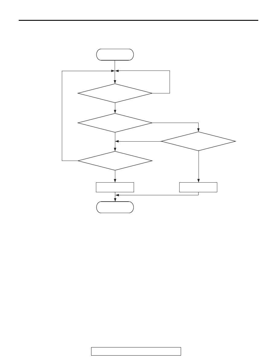
DTC SET CONDITIONS
Logic Flow Chart
.
Check Conditions
• 3 seconds or more have passed since the ignition
switch was turned to "ON" position.
Judgement Criterion
• Mass airflow sensor output voltage has continued
to be 0.2 volt or lower for 2 seconds.
.
OBD-II DRIVE CYCLE PATTERN
Refer to Diagnostic Function
− OBD-II Drive Cycle −
Pattern 22
.
TROUBLESHOOTING HINTS (The most
likely causes for this code to be set are: )
• Mass airflow sensor failed.
• Connector damage
• Harness damage
• ECM failed.
DIAGNOSIS
Required Special Tools:
• MB991958: Scan tool (M.U.T.-III Sub Assembly)
• MB991824: V.C.I.
• MB991827: USB Cable
• MB991910: Main Harness A
End
Malfunction
Yes
Yes
Yes
No
No
No
Continuous
failure for 2secs
Output voltage
< 0.2V
Output voltage
> 4.9V
Monitoring
conditions
Good
Start
AK700459
Yes
No