Mitsubishi Outlander GS45X. Manual - part 800
MULTIPORT FUEL INJECTION (MFI) DIAGNOSIS
TSB Revision
MULTIPORT FUEL INJECTION (MFI) <3.0L ENGINE>
13B-133
.
CIRCUIT OPERATION
• The mass airflow sensor power is supplied from
the MFI relay (terminal No. 2), and the ground is
provided on the ECM (terminal No. 88).
• A voltage that is according to the mass airflow
rate is sent to the ECM (terminal No. 87) from the
mass airflow sensor output terminal (terminal No.
3).
.
TECHNICAL DESCRIPTION
• While the engine is running, the mass airflow
sensor outputs voltage which corresponds to the
mass airflow rate.
• The ECM checks whether the voltage output by
the mass airflow sensor while the engine is run-
ning is within a specified range.
.
DESCRIPTIONS OF MONITOR METHODS
Compare load value with mass airflow sensor output
voltage.
.
MONITOR EXECUTION
Continuous
.
MONITOR EXECUTION CONDITIONS
(Other monitor and Sensor)
Other Monitor (There is no temporary DTC stored
in memory for the item monitored below)
• Not applicable
Sensor (The sensor below is determined to be
normal)
• Throttle position sensor
.
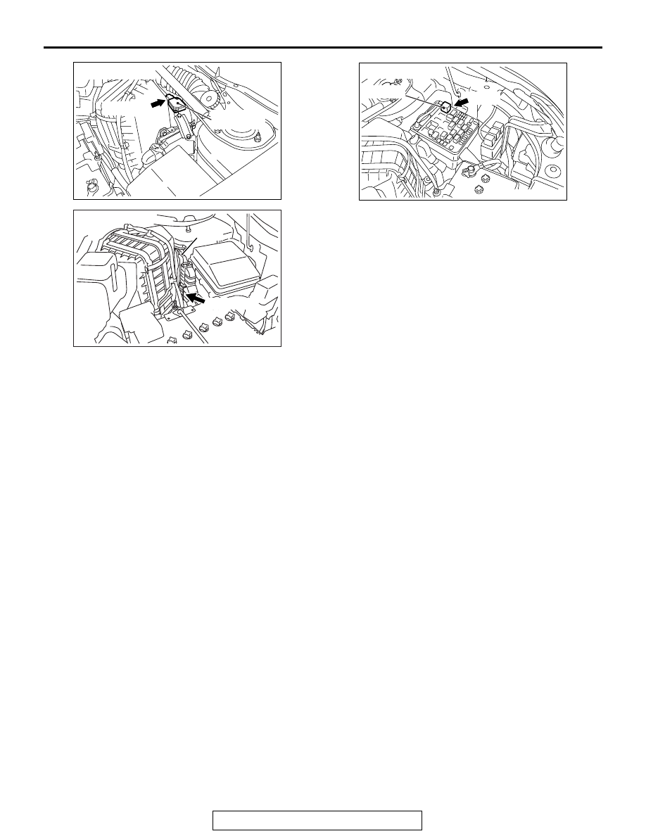
AK700406
AB
Mass airflow
sensor
A-07 (GR)
Connector: A-07
AK700402AB
ECM
B-11 (GR)
Connector: B-11
AK700399AB
MFI relay
A-33X
Connector: A-33X