Mitsubishi Outlander GS45X. Manual - part 765


  Index      Mitsubishi     Mitsubishi Outlander GS45X - service repair manual


Search            


Content   ..  763  764  765  766   ..


Mitsubishi Outlander GS45X. Manual - part 765


INJECTOR

TSB Revision

MULTIPORT FUEL INJECTION (MFI) <2.4L ENGINE>

13A-883

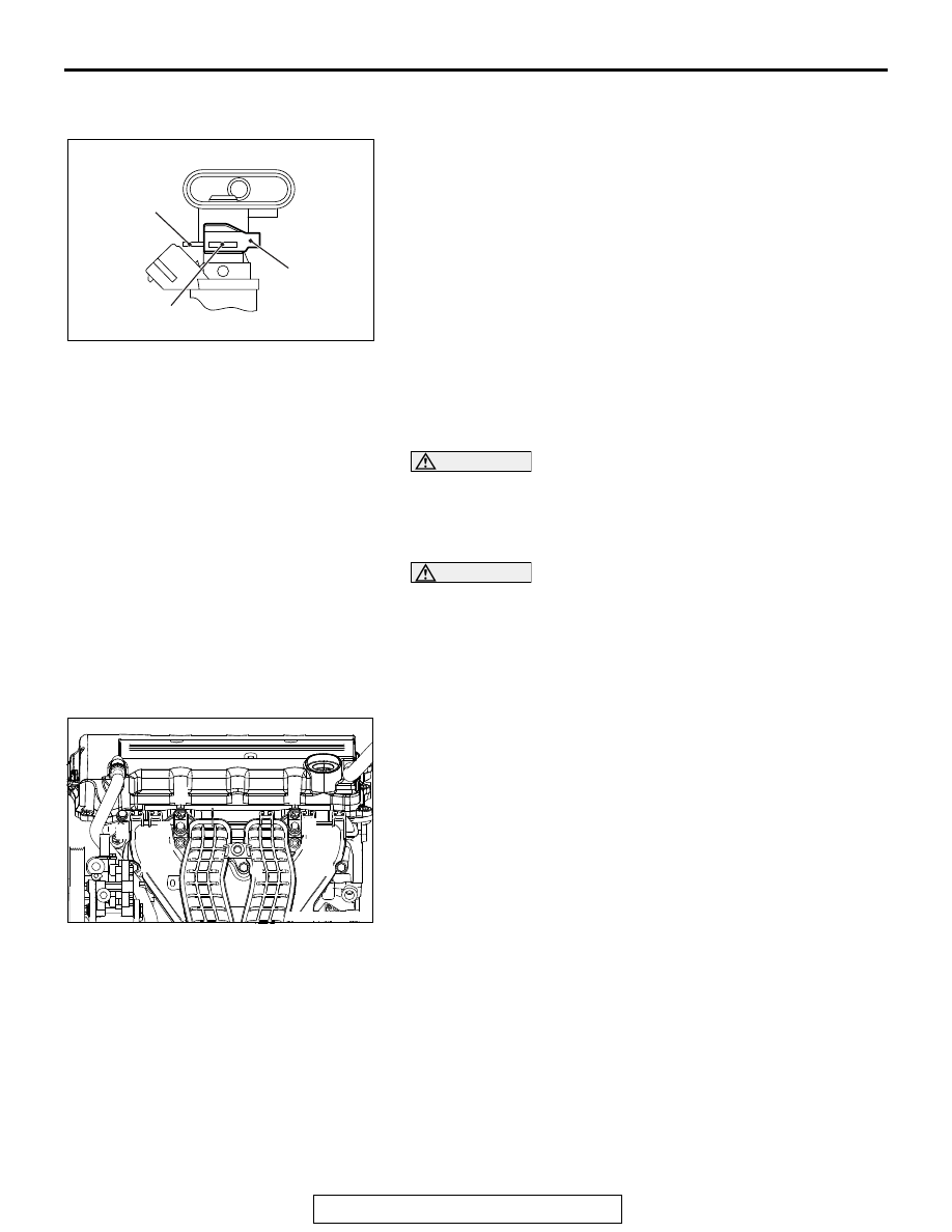
>>D<< FUEL INJECTOR SUPPORT 
INSTALLATION

Install the fuel injector support to the fuel injector groove and 
fuel rail flange, and fix the fuel injector assembly and fuel rail.

.

>>E<< FUEL RAIL AND FUEL INJECTOR 
ASSEMBLY/BRACKET/INJECTOR PROTECTOR 
REAR INSTALLATION

CAUTION

When applying the engine oil, make sure not to allow the 
engine oil to enter the intake manifold inside.
1. Apply a small amount of new engine oil to the O-ring at the 

end of fuel injector assembly.

CAUTION

When installing the fuel rail and fuel injector assembly to 
the intake manifold, pay attention to avoid damage to the 
O-ring at the end of the fuel injector assembly.
2. Install the fuel rail and fuel injector assembly to the intake 

manifold.

3. Install the bracket and injector protector rear.
4. Loosen the intake manifold mounting bolts and nuts (Bolts 

and nuts 1, 2, 3, and 9 shown in the figure).

5. Remove the EGR valve (Refer to GROUP 17, Emission 

Control 

− Exhaust Gas Recirculation (EGR) Valve <2.4L 

Engine>

P.17-84

 ).

6. Loosen the EGR valve support and intake manifold coupling 

bolts (Refer to GROUP 17, Emission Control 

− Exhaust Gas 

Recirculation (EGR) Valve <2.4L Engine>

P.17-84

 ).

7. Loosen the intake manifold stay mounting bolts (Refer to 

GROUP 15, Intake Manifold <2.4L Engine>

P.15-9

 ).

8. Temporarily tighten the mounting bolts and nuts of the inlet 

manifold, bracket, fuel rail and injector protector rear to the 
specified torque in the order of number shown in the figure.

Tightening torque: 3.5 

± 1.5 Nm (31 ± 13 in-lb)

9. Tighten the mounting bolts and nuts of the inlet manifold, 

bracket, fuel rail and injector protector rear to the specified 
torque in the order of number shown in the figure again.

Tightening torque: 20 

± 2 Nm (15 ± 1 ft-lb)

10.Tighten the inlet manifold stay mounting bolts to the 

specified torque (Refer to GROUP 15, Intake Manifold <2.4L 
Engine>

P.15-9

 ).

AC312109

AC

Fuel rail brim

Fuel injector
support

Fuel injector
groove

AC507953AB

10

3

5

7

1

6

4

2

9

8

INJECTOR

TSB Revision

MULTIPORT FUEL INJECTION (MFI) <2.4L ENGINE>

13A-884

Tightening torque: 20 

± 2 Nm (15 ± 1 ft-lb)

11.Tighten the EGR valve support and intake manifold coupling 

bolts to the specified torque (Refer to GROUP 17, Emission 
Control 

− Exhaust Gas Recirculation (EGR) Valve <2.4L 

Engine>

P.17-84

 ).

Tightening torque: 20 

± 2 Nm (15 ± 1 ft-lb)

12.Install the EGR valve (Refer to GROUP 17, Emission 

Control 

− Exhaust Gas Recirculation (EGR) Valve <2.4L 

Engine>

P.17-84

 ).

.

>>F<< FUEL HIGH-PRESSURE HOSE 
CONNECTION

1. Pull up the retainer of fuel high-pressure hose to unlock 

before installing.

2. Securely insert the fuel rail stopper into the fuel 

high-pressure hose connector groove to install the fuel 
high-pressure hose to the fuel rail.

CAUTION

• When pushing in the retainer of the fuel high-pressure 

hose connector, pay attention to avoid damage to the 
retainer.

• After the installation of the fuel high-pressure hose, 

slightly pull the fuel high-pressure hose to check that it 
is connected securely. At this time, also check that 
there is approximately 1 mm (0.04inch) play.

3. Push in the retainer of the fuel high-pressure hose 

connector to lock the fuel high-pressure hose and fuel rail.

AC606113

Fuel high-pressure
hose

Retainer

AB

AC506794 AB

Fuel high-pressure
hose

Fuel rail

Retainer

Stopper

THROTTLE BODY ASSEMBLY

TSB Revision

MULTIPORT FUEL INJECTION (MFI) <2.4L ENGINE>

13A-885

THROTTLE BODY ASSEMBLY

REMOVAL AND INSTALLATION

M1131007702261

CAUTION

• When the throttle body assembly replacement is performed, use scan tool MB991958 to initialize 

the learning value (Refer to GROUP 00, Precautions Before Service 

 Initialization Procedure for 

Learning Value in MFI Engine 

P.00-53

).

• Never loosen the screw fixing the throttle body assembly resin cover. If the screw is loosened, the 

sensor incorporated in the resin cover is misaligned and the throttle body assembly does not 
work normally.

Pre-removal operation
• Engine Upper Cover Removal (Refer to GROUP 11A, 

Camshaft 

P.11A-26

).

• Engine Coolant Draining (Refer to GROUP 14, On-vehicle 

Service 

− Engine Coolant Replacement 

P.14-26

).

• Air Cleaner Intake Hose Removal (Refer to GROUP 15, 

Air Cleaner <2.4L Engine>

P.15-4

).

Post-installation operation
• Air Cleaner Intake Hose Installation (Refer to GROUP 15, 

Air Cleaner <2.4L Engine>

P.15-4

).

• Engine Coolant Refilling (Refer to GROUP 14, On-vehicle 

Service 

− Engine Coolant Replacement 

P.14-26

).

• Engine Upper Cover Installation (Refer to GROUP 11A, 

Camshaft 

P.11A-26

).

AC609824AB

2

4

9

1

N

5

7

8

9.5 ± 2.5 N·m
88 ± 22 in-lb

3

6

9.5 ± 2.5 N·m
88 ± 22 in-lb

20 ± 2 N·m
15 ± 1 ft-lb

Removal steps 

>>

B

<<

Initialization operation (only at 
installation)

1.

Throttle body assembly connector 
connection

2.

Control wiring harness clip 
connection

3.

Battery wiring harness clamp 
connection

4.

Throttle body water feed hose 
connection

5.

Throttle body water return hose 
connection

6.

Throttle body stay

7.

Throttle body wiring harness 
connector bracket

8.

Throttle body assembly

>>

A

<<

9.

Throttle body gasket

Removal steps (Continued)

THROTTLE BODY ASSEMBLY

TSB Revision

MULTIPORT FUEL INJECTION (MFI) <2.4L ENGINE>

13A-886

INSTALLATION SERVICE POINTS

.

>>A<< THROTTLE BODY GASKET INSTALLA-
TION

Fit the throttle body gasket in the intake manifold groove 
securely with neither twisting nor damage given.

.

>>B<< INITIALIZATION OPERATION

Turn the ignition switch to the "ON" position and then to 
"LOCK" (OFF) position and hold it for at least 10 seconds.

AC506797

AC

Intake
manifold

Throttle body
gasket


Content   ..  763  764  765  766   ..