Mitsubishi Outlander GS45X. Manual - part 610
MULTIPORT FUEL INJECTION (MFI) DIAGNOSIS
TSB Revision
MULTIPORT FUEL INJECTION (MFI) <2.4L ENGINE>
13A-263
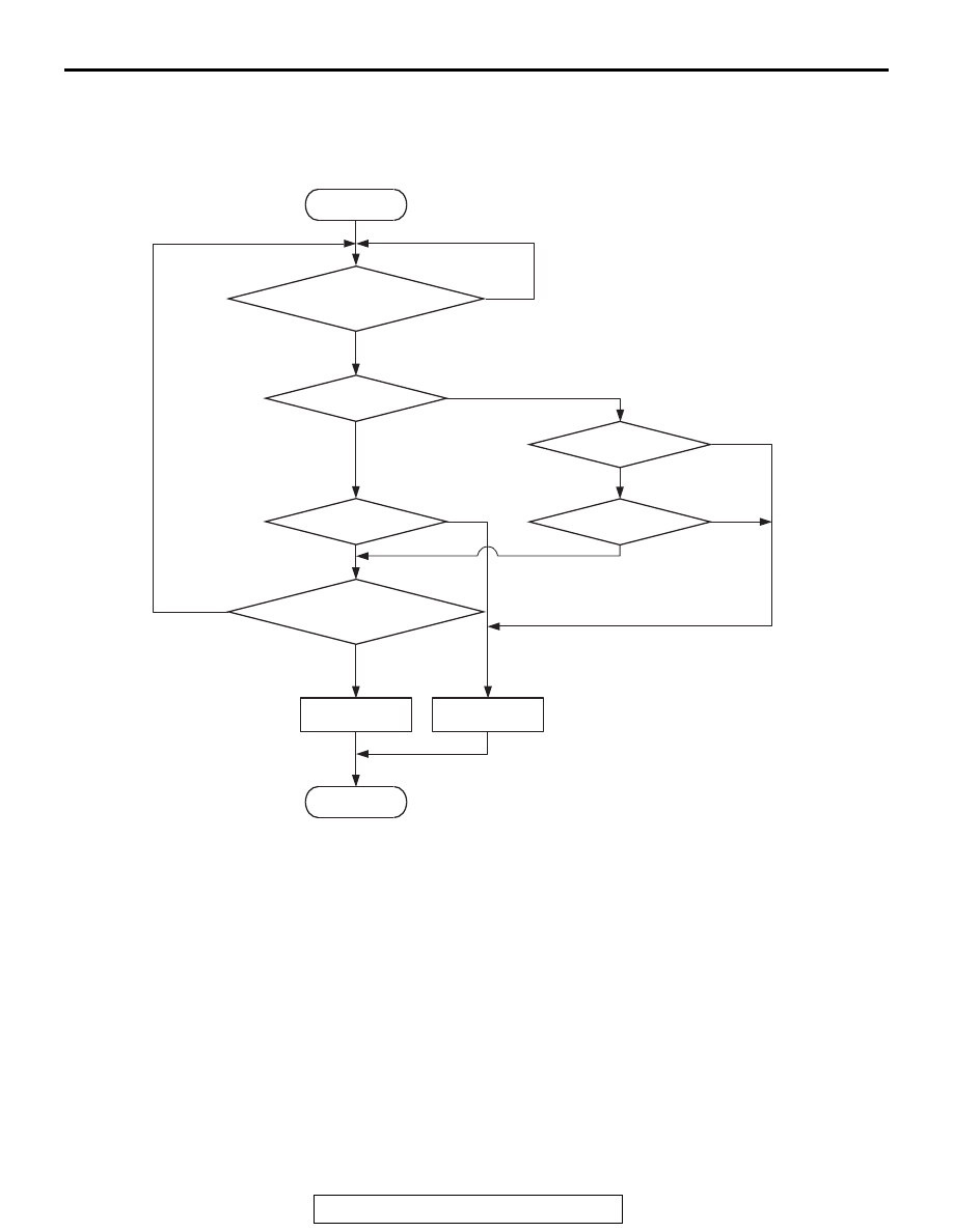
DTC SET CONDITIONS
Logic Flow Chart
.
Check Conditions
• Engine coolant temperature is lower than 100°C
(212
°F) when the engine is started.
• Intake air temperature is lower than 60°C (140°F)
when the engine is started.
• Under the closed loop air/fuel ratio control.
• Engine coolant temperature is higher than 76°C
(169
°F).
• Mass airflow sensor output is 9 g/sec or more.
Judgement Criterion
• Long-term fuel trim has continued to be higher
than +12.5 percent for 5 seconds.
or
• Short-term fuel trim has continued to be higher
than +5.5 percent for 5 seconds.
Check Conditions
• Engine coolant temperature is lower than 100°C
(212
°F) when the engine is started.
• Intake air temperature is lower than 60°C (140°F)
when the engine is started.
• Under the closed loop air/fuel ratio control.
• Engine coolant temperature is higher than 76°C
(169
°F).
• Mass airflow sensor output is 9 g/sec or less.
End
No
No
No
No
No
No
Malfunction
Good
AK604328
Start
Yes
Yes
Yes
Yes
Yes
Yes
Continuous
failure for 5secs
Monitoring
conditions
K
LRN
>= K0
K
LRN
<= K2
K
I
>= K1
K
I
<= K3
K
LRN
: Long-term trim
K
I
: Short-term trim
K0 : Maximum limit of long-term trim
K2 : Minimum limit of long-term trim
K1 : Maximum limit of short-term trim
K3 : Minimum limit of short-term trim