Mitsubishi Outlander GS45X. Manual - part 609
MULTIPORT FUEL INJECTION (MFI) DIAGNOSIS
TSB Revision
MULTIPORT FUEL INJECTION (MFI) <2.4L ENGINE>
13A-259
.
CIRCUIT OPERATION
• A voltage corresponding to the oxygen concen-
tration in the exhaust gas is sent to the ECM (ter-
minal No. 40) from the output terminal (terminal
No. 3) of the heated oxygen sensor (rear).
• Terminal No. 4 of the heated oxygen sensor
(rear) is grounded with ECM (terminal No. 41).
• The ECM applies an offset voltage of 0.5 volt to
terminal No. 4 of the heated oxygen sensor
(rear).
.
TECHNICAL DESCRIPTION
• The output signal of the linear air-fuel ratio sensor
is compensated by the output signal of the
heated oxygen sensor (rear).
• The ECM checks for the heated oxygen sensor
(rear) output voltage.
.
DESCRIPTIONS OF MONITOR METHODS
Heated oxygen sensor (rear) output voltage does not
change during specified go/stop operations
including fuel cut are repeated.
.
MONITOR EXECUTION
Continuous
.
MONITOR EXECUTION CONDITIONS
(Other monitor and Sensor)
Other Monitor (There is no temporary DTC stored
in memory for the item monitored below)
• Linear air-fuel ratio sensor monitor
• Linear air-fuel ratio sensor heater monitor
• Heated oxygen sensor (rear) heater monitor
• Heated oxygen sensor offset voltage monitor
Sensor (The sensor below is determined to be
normal)
• Mass airflow sensor
• Engine coolant temperature sensor
• Intake air temperature sensor
• Barometric pressure sensor
.
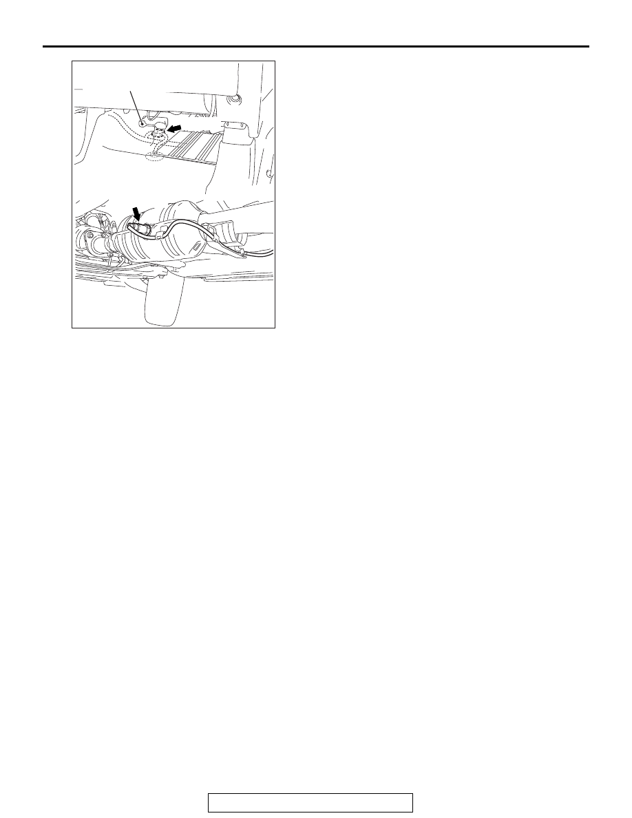
AK900665
D-37 (B)
Rear heater duct (RH)
Heated oxygen
sensor (rear)
AB
Connector: D-37