Mitsubishi Outlander GS45X. Manual - part 542
ENGINE ROLL STOPPER AND CENTERMEMBER
TSB Revision
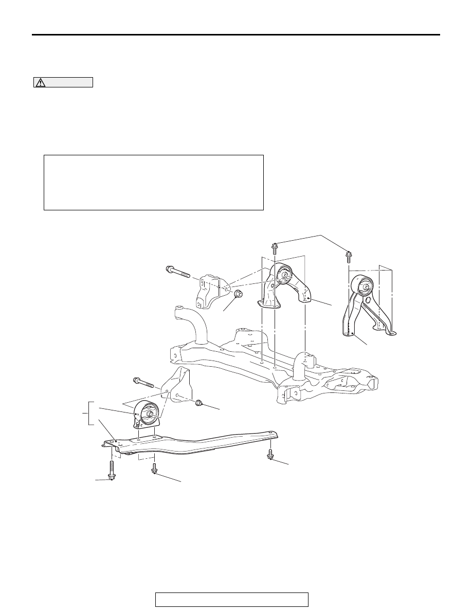
POWER PLANT MOUNT
32-11
ENGINE ROLL STOPPER AND CENTERMEMBER
REMOVAL AND INSTALLATION
M1321002301644
CAUTION
• When the engine mounting insulator, transaxle mounting insulator and rear roll stopper have been
removed, tighten the engine mounting insulator, transaxle mounting insulator and rear roll stop-
per securely. Then, tighten the front roll stopper center nut *
1
securely.
• The parts indicated by the *2 are the bolts with friction coefficient stabilizer. In removal, ensure
there is no damage, clean dust and soiling from bearing and thread surfaces, and tighten them to
the specified torque.
Pre-removal and post-installation operation
• Engine Room Under Cover Front A<AWD>, B, and C Removal
and Installation (Refer to GROUP 51, Under Cover
).
<2.4L ENGINE>
• Engine Room Under Cover Front Removal and Installation (Refer
to GROUP 51, Under Cover
). <3.0L ENGINE>
AC702793
1
2
3
4
AD
50 ± 5 N·m
37 ± 3 ft-lb
50 ± 5 N·m
37 ± 3 ft-lb
1
2
<FWD>
<AWD>
2
1
2
2
53 ± 8 N·m
40 ± 5 ft-lb
71 ± 10 N·m*
52 ± 7 ft-lb*
56 ± 5 N·m*
41 ± 3 ft-lb*
71 ± 10 N·m*
52 ± 7 ft-lb*
4
Front roll stopper and
centermember removal steps
1.
Front roll stopper and
centermember assembly
2.
Centermember
>>A<<
3.
Front roll stopper
Rear roll stopper removal steps
•
Transfer assembly <AWD> (Refer to
GROUP 23A, Transfer Assembly
) <CVT>, Refer to
GROUP 23C, Transfer Assembly
<Vehicles without
S-AWC>) <A/T>.
4.
Rear roll stopper