Mitsubishi Outlander GS45X. Manual - part 538


  Index      Mitsubishi     Mitsubishi Outlander GS45X - service repair manual


Search            


Content   ..  536  537  538  539   ..


Mitsubishi Outlander GS45X. Manual - part 538


IGNITION SYSTEM

TSB Revision

ENGINE ELECTRICAL

16-51

REMOVAL AND INSTALLATION <3.0L ENGINE>

M1163003401606

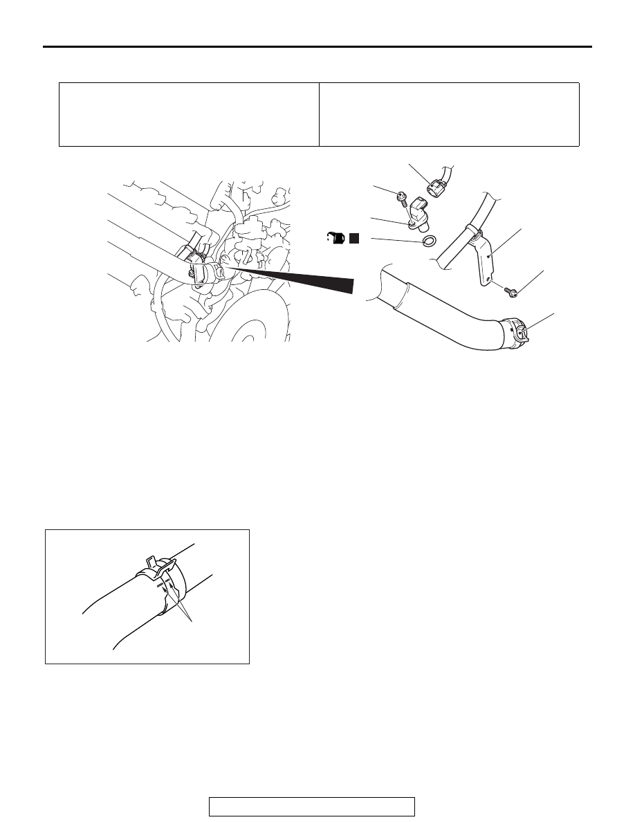
REMOVAL SERVICE POINT

.

<<A>> RADIATOR UPPER HOSE DISCONNEC-
TION

Make mating marks on the radiator upper hose and the hose 
clamp. Disconnect the radiator upper hose.

Pre-removal Operation
• Engine Coolant Draining (Refer to GROUP 14, On-vehicle 

Service 

− Engine Coolant Change 

P.14-26

).

• Battery and Battery Tray Removal (Refer to GROUP 54A, 

Battery 

P.54A-11

).

Post-installation Operation
• Battery and Battery Tray Installation (Refer to GROUP 

54A, Battery 

P.54A-11

).

• Engine Coolant Refilling (Refer to GROUP 14, On-vehicle 

Service 

− Engine Coolant Change 

P.14-26

).

AC703804

1

2

3

4

5

9.5 ± 2.5 N·m
84 ± 22 in-lb

11 ± 1 N·m
98 ± 8 in-lb

N

AC

(Engine oil)

Removal steps 

<<

A

>> >>

A

<< 1.

Radiator upper hose connection

2.

Harness bracket 

3.

Camshaft position sensor 
connector connection

4.

Camshaft position sensor

5.

O-ring

Removal steps (Continued)

AC703115

Mating marks

AB

IGNITION SYSTEM

TSB Revision

ENGINE ELECTRICAL

16-52

INSTALLATION SERVICE POINT

.

>>A<< RADIATOR UPPER HOSE CONNECTION

1. Insert radiator upper hose as far as the projection of the 

thermostat housing.

2. Align the mating marks on the radiator upper hose and hose 

clamp, and then connect the radiator upper hose.

CRANKSHAFT POSITION SENSOR

REMOVAL AND INSTALLATION <2.4L ENGINE>

M1163004801696

AC703117

Mating marks

Projection

Thermostat housing

AD

Pre-removal and post-installation operation
• Air Cleaner Assembly Removal and Installation (Refer to 

GROUP 15, Air Cleaner 

P.15-4

).

AC506702AL

1

2

3

4

N

11 ± 1 N·m
97 ± 8 in-lb

(Engine oil)

11 ± 1 N·m
97 ± 8 in-lb

<AWD>
49 ± 6 N·m
36 ± 4 in-lb

Removal steps 

1.

Crankshaft position sensor 
connector connection

2.

Crankshaft position sensor

3.

O-ring

Exhaust manifold bracket (Refer 
to GROUP 15, Exhaust Manifold 

P.15-15

) <FWD>.

4.

Crankshaft position sensor cover

Removal steps (Continued)

IGNITION SYSTEM

TSB Revision

ENGINE ELECTRICAL

16-53

REMOVAL AND INSTALLATION <3.0L ENGINE>

M1163003500923

Pre-removal operation
• Engine Room Side Cover (RH) Removal (Refer to 

GROUP 51 

− Under Cover 

P.51-22

).

• Driveshaft Assembly (RH) Removal <Vehicles with 

S-AWC> (Refer to GROUP 26 

− Driveshaft Assembly 

P.26-23

).

Post-installation operation
• Driveshaft Assembly (RH) Installation <Vehicles with 

S-AWC> (Refer to GROUP 26 

− Driveshaft Assembly 

P.26-23

).

• Engine Room Side Cover (RH) Installation (Refer to 

GROUP 51 

− Under Cover 

P.51-22

). 

AC703805

9.5 ± 2.5 N·m
84 ± 22 in-lb

4

N

1

2

3

AC

(Engine oil)

Removal steps 

1.

Harness clamp

2.

Crankshaft position sensor 
connector connection

3.

Crankshaft position sensor

4.

O-ring

Removal steps (Continued)

IGNITION SYSTEM

TSB Revision

ENGINE ELECTRICAL

16-54

KNOCK SENSOR

REMOVAL AND INSTALLATION <2.4L ENGINE>

M1163002801894

CAUTION

• When the knock sensor replacement is performed, use scan tool MB991958 to initialize the learn-

ing value (Refer to GROUP 00, Precautions Before Service 

 Initialization Procedure for Learning 

Value in MFI Engine 

P.00-53

).

• Do not drop or hit the knock sensor against other components. Internal damage may result, and 

the knock sensor will need to be replaced.

Pre-removal and post-installation operation
• Intake Manifold Assembly Removal and Installation (Refer 

to GROUP 15, Intake Manifold <2.4L Engine>

P.15-9

).

AC506683

1

2

20 ± 2 N·m
15 ± 1 ft-lb

AB

Removal steps 

1.

Knock sensor connector 
connection

2.

Knock sensor


Content   ..  536  537  538  539   ..