Mitsubishi Outlander GS45X. Manual - part 484
TIMING CHAIN
TSB Revision
ENGINE MECHANICAL <2.4L ENGINE>
11A-67
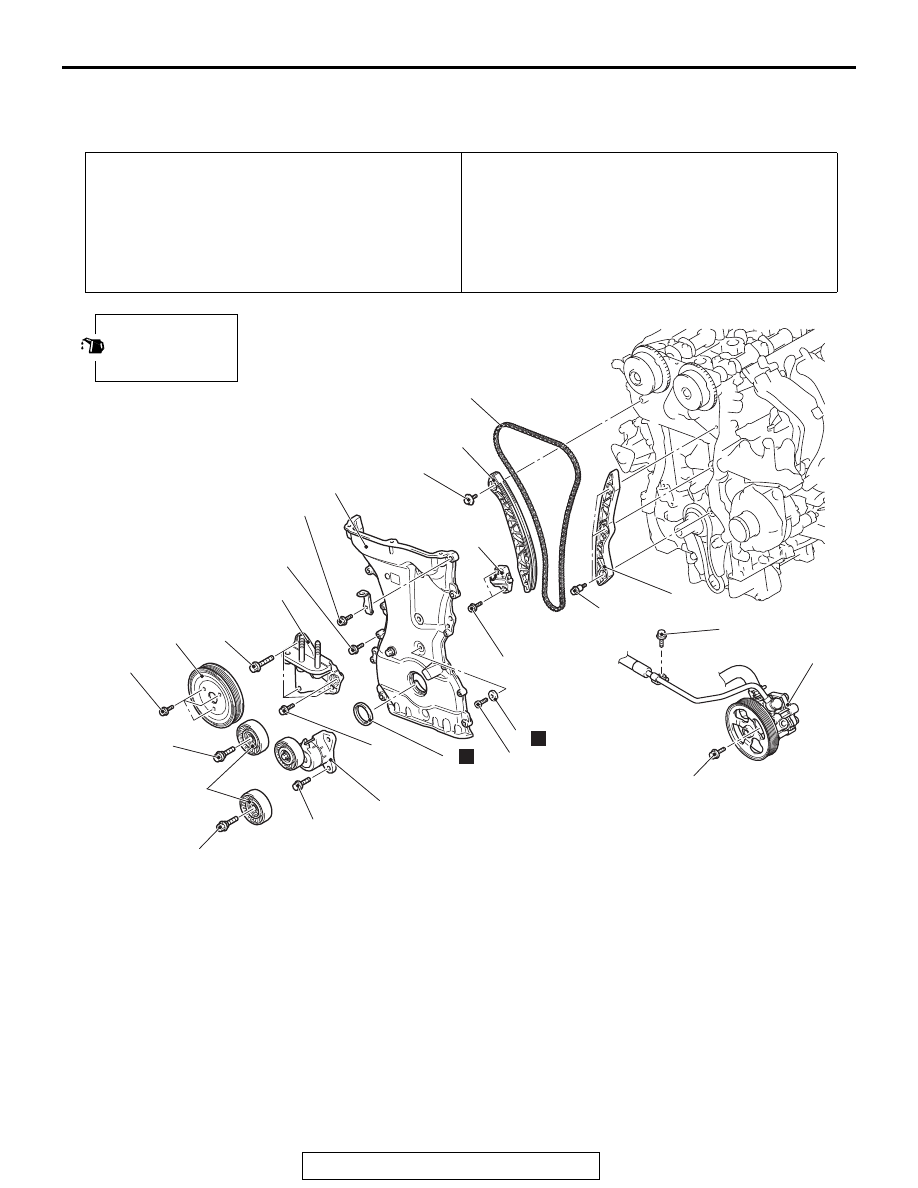
TIMING CHAIN
REMOVAL AND INSTALLATION
M1112007201877
Pre-removal operation
• Engine Room Under Cover Front B and Engine Room
Side Cover (RH) Removal (Refer to GROUP 51, Under
Cover
P.51-23
).
• Engine Oil Draining (Refer to GROUP 12, On-vehicle Ser-
vice
− Engine Oil Replacement
).
• Rocker Cover Assembly Removal (Refer to
).
• Engine Oil Pan Removal (Refer to
Post-installation operation
• Engine Oil Pan Installation (Refer to
• Rocker Cover Assembly Installation (Refer to
).
• Engine Oil Refilling (Refer to GROUP 12, On-vehicle Ser-
vice
− Engine Oil Replacement
).
• Engine Room Under Cover Front B and Engine Room
Side Cover (RH) Installation (Refer to GROUP 51, Under
Cover
P.51-23
).
AC700425AG
1
2
3
5
7
9
10
11
12
6
N
Apply engine oil to all
moving parts before
installation.
4
8
N
24 ± 4 N·m
18 ± 2 ft-lb
48 ± 6 N·m
35 ± 4 ft-lb
48 ± 7 N·m
36 ± 5 ft-lb
22 ± 4 N·m
16 ± 3 ft-lb
9.0 ± 1.0 N·m
80 ± 9 in-lb
26 ± 3 N·m
19 ± 2 ft-lb
10 ± 2 N·m
89 ± 17 in-lb
48 ± 7 N·m
36 ± 5 ft-lb
10 ± 2 N·m
89 ± 17 in-lb
10 ± 2 N·m
89 ± 17 in-lb
10 ± 2 N·m
89 ± 17 in-lb
10 ± 2 N·m
89 ± 17 in-lb
25 ± 4 N·m
18 ± 3 ft-lb
13 ± 2 N·m
111 ± 2 in-lb
Removal steps
<<
A
>>
•
Crankshaft pulley (Refer to
>>
E
<< 1.
Water pump pulley
2.
Idler pulley
3.
Auto-tensioner
<<
B
>>
4.
Power steering oil pump assembly
<<
C
>>
•
Engine and transaxle assembly
holding
•
Engine mounting insulator (Refer to
GROUP 32, Engine Mounting
)
5.
Cylinder block engine front
mounting bracket
6.
Gasket
<<
D
>> >>
D
<< 7.
Timing chain case assembly
>>
C
<< 8.
Crankshaft front oil seal
<<
E
>> >>
B
<< 9.
Timing chain tensioner
10. Timing chain tension side guide
>>
A
<< 11. Timing chain
12. Timing chain loose side guide
Removal steps (Continued)