Mitsubishi Outlander GS45X. Manual - part 482


  Index      Mitsubishi     Mitsubishi Outlander GS45X - service repair manual


Search            


Content   ..  480  481  482  483   ..


Mitsubishi Outlander GS45X. Manual - part 482


CYLINDER HEAD GASKET

TSB Revision

ENGINE MECHANICAL <2.4L ENGINE>

11A-59

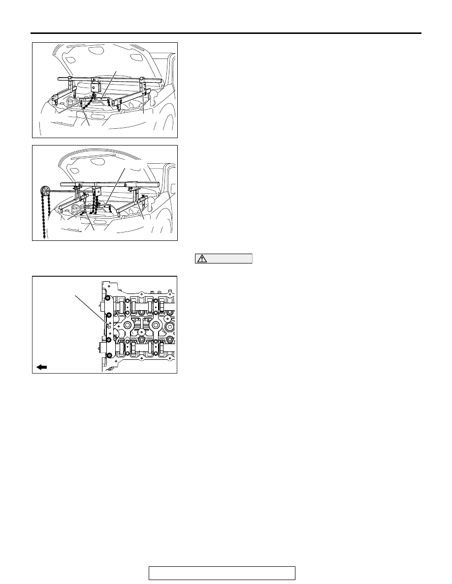
3. Remove special tool engine hanger (MB991928 or 

MB991895) which was installed for supporting the engine 
and transaxle assembly when the valve timing chain was 
removed.

CAUTION

Be careful not to drop the camshaft bearing.
4. Loosen the mounting bolts of front camshaft bearing cap in 

the order of number shown in the figure, and remove the 
front camshaft bearing cap assembly.

.

AC506487

AE

MB991527

MB991454

MB991928

MB991956

AC506484

MB991527

AE

MB991454

MB991956

MB991895

AC506745

AD

1

2

3

4

Engine front

Front camshaft
bearing cap
assembly

CYLINDER HEAD GASKET

TSB Revision

ENGINE MECHANICAL <2.4L ENGINE>

11A-60

<<C>> CAMSHAFT BEARING OIL FEEDING 
CAP/CAMSHAFT BEARING CAP/CAMSHAFT 
BEARING THRUST CAP REMOVAL

CAUTION

When the camshaft bearing cap mounting bolts are loos-
ened at once, the mounting bolts jump out by the spring 
force and the threads are damaged. Always loosen the 
mounting bolts in four or five steps.
Loosen the mounting bolts of the camshaft bearing caps in the 
order of number shown in the figure in four or five steps, and 
remove the camshaft bearing caps.

.

<<D>> CYLINDER HEAD BOLT/CYLINDER HEAD 
BOLT ASSEMBLY REMOVAL

Loosen and remove the bolts in two or three steps in the order 
of number shown in the figure. 

AC506746

AC

1

1

2

2

3

3

4

4

5

5

6

6

7

7

8

8

Engine front

Camshaft bearing cap

Camshaft bearing cap

AC506767AD

1

2

3

4

5

6

7

8

9

10

Engine front

CYLINDER HEAD GASKET

TSB Revision

ENGINE MECHANICAL <2.4L ENGINE>

11A-61

INSTALLATION SERVICE POINTS

.

>>A<< CYLINDER HEAD GASKET/CYLINDER 
HEAD ASSEMBLY INSTALLATION

CAUTION

Do not allow any foreign materials get into the coolant pas-
sages, oil passages and cylinder.
1. Remove the sealant and grease on the top surface of 

cylinder block and on the bottom surface of the cylinder 
head. Then, use the white gasoline or the like to degrease 
the sealant application surface.

2. Apply the sealant to the top surface of cylinder block as 

shown in the figure.

Specified sealant: ThreeBond 1217G or equivalent

NOTE: Install the cylinder head gasket immediately after 
applying sealant.

3. Install the cylinder head gasket to the cylinder block.

NOTE: When the cylinder head gasket is installed to the cyl-
inder block, check that the sealant is securely applied to the 
bead line of the cylinder head gasket.

4. Apply the sealant to the top surface of cylinder head gasket 

as shown in the figure.

Specified sealant: ThreeBond 1217G or equivalent

NOTE: Install the cylinder head assembly immediately after 
applying sealant.

CAUTION

After the installation, until a sufficient period of time (one 
hour or more) elapses, do not apply the oil or water to the 
sealant application area or start the engine.
5. Install the cylinder head assembly.

.

AC607682AB

Degrease

Degrease

Bottom view of cylinder head

Top view of cylinder block

AC511063

AD

φ 2 mm or φ 3 mm (φ 0.08 in or φ 0.12 in)

Cylinder head
gasket

Cylinder head 
gasket

Cylinder 
block

φ 2 mm or φ 3 mm
(

φ 0.08 in or φ 0.12 in)

CYLINDER HEAD GASKET

TSB Revision

ENGINE MECHANICAL <2.4L ENGINE>

11A-62

>>B<< CYLINDER HEAD BOLT 
ASSEMBLY/CYLINDER HEAD BOLT 
INSTALLATION

1. Replace cylinder head bolts with a new ones.
2. For two cylinder head bolts of the timing chain side, the 

washer can be removed from the bolt. Install the washer, 
with its sag facing upward, to the cylinder head bolts.

3. Apply a small amount of engine oil to the cylinder head bolt 

threads and the washers.

4. Tighten the cylinder head bolts by the following procedure 

(plastic region angular tightening method.)

(1) Tighten the cylinder head bolts to the specified torque in 

the order of number shown in the figure.

Tightening torque: 35 

± 2 Nm (26 ± 1 ft-lb)

CAUTION

• When the tightening angle is smaller than the specified 

tightening angle, the appropriate tightening capacity 
cannot be secured.

• When the tightening angle is larger than the specified 

tightening angle, remove the cylinder head bolt to start 
from the beginning again according to the procedure.

(2) Apply paint marks to the head of cylinder head bolt and 

the cylinder head.

(3) Tighten the cylinder head bolt to 90 degrees angle in the 

tightening order. Additionally tighten to 90 degrees angle, 
and check that the paint mark on the cylinder head bolt is 
aligned with the paint mark on the cylinder head.

AC506767AE

1

2

3

4

5

6

7

8

9

10

Engine front

AC708680AC

90˚

90˚

Paint mark

Paint mark

Paint marks

Paint marks


Content   ..  480  481  482  483   ..