Mitsubishi Outlander GS45X. Manual - part 347


  Index      Mitsubishi     Mitsubishi Outlander GS45X - service repair manual


Search            


Content   ..  345  346  347  348   ..


Mitsubishi Outlander GS45X. Manual - part 347


ABS DIAGNOSIS

TSB Revision

ANTI-LOCK BRAKING SYSTEM (ABS)

35B-9

NOTE: 

.

*1

 This DTC is not set within the vehicle speed of 12 mph (20 km/h) or less.

*2

 Turns ON when two or more wheels are faulty.

*3

 Stays ON until the vehicle speed reaches 6 mph (10 km/h) when the ignition switch is turned to ON next 

time, even if the malfunction is repaired and returns to normal condition.

*4

 May not illuminate depending on the trouble cause.
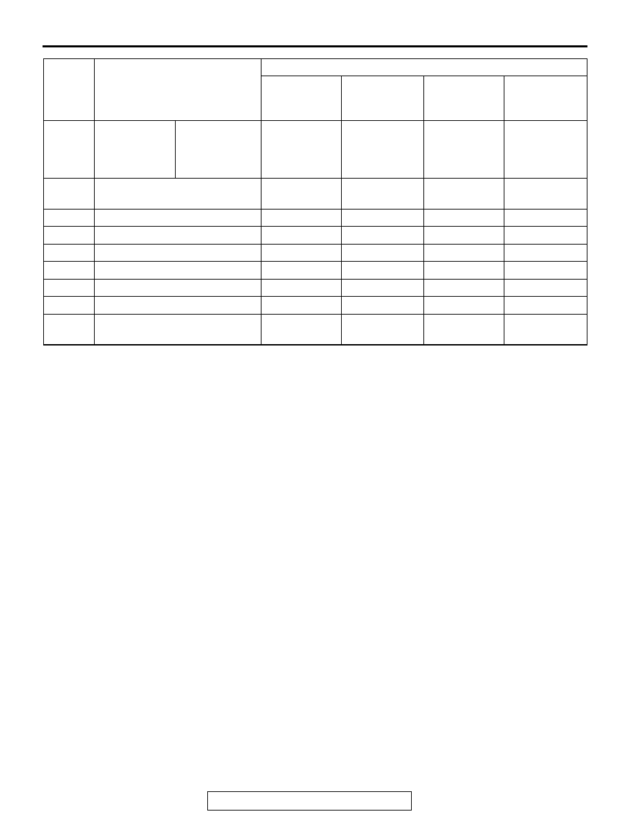
C2101

Battery 
voltage 
problem (high 
voltage)

18.0 

± 1.0 V or 

more

Illuminates

Illuminates

Illuminates

Illuminates

C1395

Brake fluid charging 
incompletion

Extinguished

Extinguished

Flashes (1 Hz) Illuminates

C2203

VIN not written

Extinguished

Extinguished

Illuminates

Illuminates

C1608

Implausible diagnosis data

Extinguished

Extinguished

Extinguished

Extinguished

U0001

Bus off

Extinguished

Extinguished

Extinguished

Extinguished

U0100

Engine time-out error

Extinguished

Extinguished

Extinguished

Extinguished

U0141

ETACS time-out error

Extinguished

Extinguished

Extinguished

Extinguished

U1415

Variant coding not implemented Extinguished

Extinguished

Illuminates

Illuminates

U1417

Invalid variant coding value 
(including wrong assembly)

Extinguished

Extinguished

Illuminates

Illuminates

DTC

Item

Countermeasures for failure
Brake 
warning light

Brake 
warning 
display

ABS warning 
light

ABS warning 
display

ABS DIAGNOSIS

TSB Revision

ANTI-LOCK BRAKING SYSTEM (ABS)

35B-10

Under EBD and ABS control in case of failure

DTC

Item

Countermeasures for failure
EBD control

ABS control

C100A

Abnormality in FL wheel speed sensor 
circuit

Executed

*2

Prohibited

C1015

Abnormality in FR wheel speed 
sensor circuit

C1020

Abnormality in RL wheel speed 
sensor circuit

C102B

Abnormality in RR wheel speed 
sensor circuit

C1011

Abnormality in FL wheel speed sensor 
signal

Executed

*2

Prohibited

C101C

Abnormality in FR wheel speed 
sensor signal

C1027

Abnormality in RL wheel speed 
sensor signal

C1032

Abnormality in RR wheel speed 
sensor signal

C1014

Mutual monitoring of FL wheel speed 
sensor

Executed

*2

Prohibited

C101F

Mutual monitoring of FR wheel speed 
sensor

C102A

Mutual monitoring of RL wheel speed 
sensor

C1035

Mutual monitoring of RR wheel speed 
sensor

C1041

Abnormality in periodical signal for FL 
wheel speed sensor

Executed

*2

Prohibited

C1042

Abnormality in periodical signal for FR 
wheel speed sensor

C1043

Abnormality in periodical signal for RL 
wheel speed sensor

C1044

Abnormality in periodical signal for RR 
wheel speed sensor

C1046

FL wheel speed sensor control phase 
time exceeded

Executed

*2

Prohibited

C1047

FR wheel speed sensor control phase 
time exceeded

C1048

RL wheel speed sensor control phase 
time exceeded

C1049

RR wheel speed sensor control phase 
time exceeded

ABS DIAGNOSIS

TSB Revision

ANTI-LOCK BRAKING SYSTEM (ABS)

35B-11

NOTE: 

.

*1

 This DTC is not set within the vehicle speed of 12 mph (20 km/h) or less.

*2

: Prohibited when two or more wheels are faulty.

*3

: Not prohibited when the brake warning lamp is not illuminated.

C104B

Abnormality in FL wheel inlet valve 
system

Prohibited

Prohibited

C104F

Abnormality in FR wheel inlet valve 
system

C1053

Abnormality in RL wheel inlet valve 
system

C1057

Abnormality in RR wheel inlet valve 
system

C105F

Abnormality in FL wheel outlet valve 
system

Prohibited

Prohibited

C1063

Abnormality in FR wheel outlet valve 
system

C1067

Abnormality in RL wheel outlet valve 
system

C105B

Abnormality in RR wheel outlet valve 
system

C2104

Malfunction of valve power supply 
circuit

Prohibited

Prohibited

C1073

Malfunction of motor drive circuit

Executed

Prohibited

C2116

Abnormality in pump motor power 
supply voltage

Executed

Prohibited

C1000

Abnormality in stop light switch circuit Executed

Executed

C2200

Trouble in ABS-ECU

Prohibited

*3

Prohibited

*3

C2100 

*1

Battery voltage 
problem (low 
voltage)

9.7 

± 0.3 V or less Executed

Prohibited

8.0 

± 0.5 V or less Prohibited

Prohibited

C2101

Battery voltage 
problem (high 
voltage)

18.0 

± 1.0 V or 

more

Prohibited

Prohibited

C1395

Brake fluid charging incompletion

Executed

Prohibited

C2203

VIN not written

Executed

Executed

C1608

Implausible diagnosis data

Executed

Executed

U0001

Bus off

Executed

Executed

U0100

Engine time-out error

Executed

Executed

U0141

ETACS time-out error

Executed

Executed

U1415

Variant coding not implemented

Executed

Prohibited

U1417

Invalid variant coding value (including 
wrong assembly)

Executed

Prohibited

DTC

Item

Countermeasures for failure
EBD control

ABS control

ABS DIAGNOSIS

TSB Revision

ANTI-LOCK BRAKING SYSTEM (ABS)

35B-12

HOW TO CONNECT THE SCAN TOOL (M.U.T.-III)

Required Special Tools:

•  MB991958: Scan Tool (M.U.T.-III Sub Assembly)

• MB991824: Vehicle Communication Interface (V.C.I.)

• MB991827: M.U.T.-III USB Cable

• MB991910: M.U.T.-III Main Harness A

CAUTION

To prevent damage to scan tool MB991958, always turn the 
ignition switch to the "LOCK" (OFF) position before con-
necting or disconnecting scan tool MB991958.
1. Ensure that the ignition switch is at the "LOCK" (OFF) 

position.

2. Start up the personal computer.
3. Connect special tool MB991827 to special tool MB991824 

and the personal computer.

4. Connect special tool MB991910 to the special tool 

MB991824.

5. Connect special tool MB991910 to the data link connector.
6. Turn the power switch special tool MB991824 to the "ON" 

position.
NOTE: When the special tool MB991824 is energized, the 
special tool MB991824 indicator light will be illuminated in a 
green color.

7. Start the M.U.T.-III system on the personal computer.
NOTE: Disconnect the scan tool MB991958 in the reverse 
order of the connecting sequence, making sure that the ignition 
switch is at the "LOCK" (OFF) position.

HOW TO READ AND ERASE DIAGNOSTIC 
TROUBLE CODES

Required Special Tools:

•  MB991958: Scan Tool (M.U.T.-III Sub Assembly)

• MB991824: Vehicle Communication Interface (V.C.I.)

• MB991827: M.U.T.-III USB Cable

• MB991910: M.U.T.-III Main Harness A

ZC501967

AC404789

AC701411AB

MB991824

MB991827

MB991910

Data link 
connector


Content   ..  345  346  347  348   ..