Mitsubishi Outlander GS45X. Manual - part 346


  Index      Mitsubishi     Mitsubishi Outlander GS45X - service repair manual


Search            


Content   ..  344  345  346  347   ..


Mitsubishi Outlander GS45X. Manual - part 346


ABS DIAGNOSIS

TSB Revision

ANTI-LOCK BRAKING SYSTEM (ABS)

35B-5

ABS WARNING LIGHT AND BRAKE WARNING 
LIGHT CHECK

M1352012001004

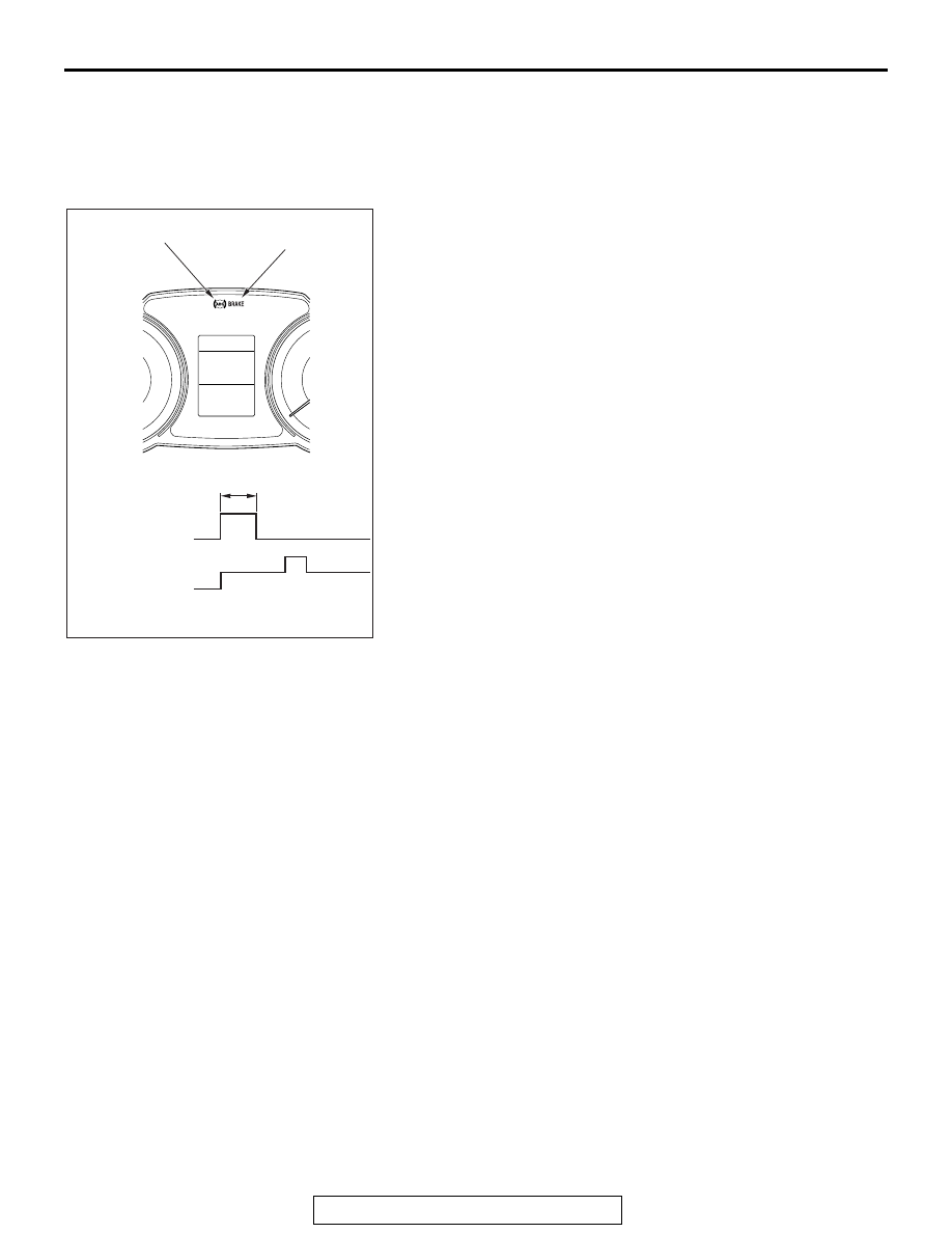
Check that ABS and brake warning lights illuminate as follows.
NOTE: The EBD warning light is also used as the brake warn-
ing light.
1. When the ignition switch is turned to the ON position, ABS 

and brake warning lights illuminate.

2. The ABS and brake warning lights illuminate for three 

seconds

*1

 and then turn OFF

*2

.

3. Otherwise, check the diagnostic trouble code.
NOTE: 

.

*1

: The ABS warning light may stay ON until the vehicle 

speed reaches 6 mph (10 km/h). As far as ABS-ECU stores 
any diagnostic trouble code related to the wheel speed sen-
sor malfunction or the motor malfunction as past trouble, 
ABS-ECU continues illuminating the ABS warning light until 
it verifies that the malfunction for that code is resolved (star-
tup check).

*2

: The brake warning light does not turn OFF when the 

parking brake is applied or the brake fluid level is lowered.

DIAGNOSIS FUNCTION

M1352011201511

ABS-ECU has the following functions for easier sys-
tem checks. The following items can be diagnosed 
using scan tool.

• Diagnostic trouble code set (Refer to 

P.35B-15

).

• Service data output (Refer to 

P.35B-179

).

• Actuator test (Refer to 

P.35B-179

).

• Freeze frame data output (Refer to 

P.35B-6

).

AC901740

ABS warning light

ABS warning
light, Brake
warning light

Ignition switch

Illuminated

Approximately 3s

ON
ACC,
LOCK

START

Brake warning light

Not
illuminated

AB

ABS DIAGNOSIS

TSB Revision

ANTI-LOCK BRAKING SYSTEM (ABS)

35B-6

CHECK OF FREEZE FRAME DATA

The freeze frame data can be checked by using the 
scan tool.

.

When detecting fault and storing the DTC, the ECU 
connected to CAN bus line obtains the data before 
the determination of the DTC and the data when the 
DTC is determined, and then stores the ECU status 
of that time. By analysing each data from scan tool, 
the troubleshooting can be performed more effi-
ciently. The displayed items are as the table below.

Display item list

Item No.

Item name

Content

Unit

1

Odometer

Total driving distance after the DTC is generated

mile

2

Ignition cycle

Number of times the ignition switch is turned "ON" or 
"LOCK (OFF)" after the past failure transition

Number of 
counts is 
displayed.

4

Accumulated minute Cumulative time for current malfunction of DTC

min

5

Power supply 
voltage

Voltage of power supply when the DTC is generated V

13

Stop light switch

Stop light switch condition when the DTC is 
generated :OFF/ON

301

ABS control

ABS control when the DTC is generated :OFF/ON

401

FL wheel speed 
sensor

Wheel speed (FL) when the DTC is generated

mph

402

FR wheel speed 
sensor

Wheel speed (FR) when the DTC is generated

mph

403

RL wheel speed 
sensor

Wheel speed (RL) when the DTC is generated

mph

404

RR wheel speed 
sensor

Wheel speed (RR) when the DTC is generated

mph

ABS DIAGNOSIS

TSB Revision

ANTI-LOCK BRAKING SYSTEM (ABS)

35B-7

FAIL-SAFE FUNCTION

If any malfunction is detected by the self-diagnostic 
function, ABS-ECU illuminates the ABS warning light 
and brake warning light

*

, and it disables ABS and 

EBD control.

NOTE: *: The brake warning light and display are 
used as EBD control warning light.

Illumination condition of warning light and display in case of failure

DTC

Item

Countermeasures for failure
Brake 
warning light

Brake 
warning 
display

ABS warning 
light

ABS warning 
display

C100A

Abnormality in FL wheel speed 
sensor circuit

Extinguished

*2

Extinguished

*2

Illuminated

*3

Illuminated

*3

C1015

Abnormality in FR wheel speed 
sensor circuit

C1020

Abnormality in RL wheel speed 
sensor circuit

C102B

Abnormality in RR wheel speed 
sensor circuit

C1011

Abnormality in FL wheel speed 
sensor signal

Extinguished

*2

Extinguished

*2

Illuminated

*3

Illuminated

*3

C101C

Abnormality in FR wheel speed 
sensor signal

C1027

Abnormality in RL wheel speed 
sensor signal

C1032

Abnormality in RR wheel speed 
sensor signal

C1014

Mutual monitoring of FL wheel 
speed sensor

Extinguished

*2

Extinguished

*2

Illuminated

*3

Illuminated

*3

C101F

Mutual monitoring of FR wheel 
speed sensor

C102A

Mutual monitoring of RL wheel 
speed sensor

C1035

Mutual monitoring of RR wheel 
speed sensor

C1041

Abnormality in periodical signal 
for FL wheel speed sensor

Extinguished

*2

Extinguished

*2

Illuminated

*3

Illuminated

*3

C1042

Abnormality in periodical signal 
for FR wheel speed sensor

C1043

Abnormality in periodical signal 
for RL wheel speed sensor

C1044

Abnormality in periodical signal 
for RR wheel speed sensor

ABS DIAGNOSIS

TSB Revision

ANTI-LOCK BRAKING SYSTEM (ABS)

35B-8

C1046

FL wheel speed sensor control 
phase time exceeded

Extinguished

*2

Extinguished

*2

Illuminated

*3

Illuminated

*3

C1047

FR wheel speed sensor control 
phase time exceeded

C1048

RL wheel speed sensor control 
phase time exceeded

C1049

RR wheel speed sensor control 
phase time exceeded

C104B

Abnormality in FL wheel inlet 
valve system

Illuminates

Illuminates

Illuminates

Illuminates

C104F

Abnormality in FR wheel inlet 
valve system

C1053

Abnormality in RL wheel inlet 
valve system

C1057

Abnormality in RR wheel inlet 
valve system

C105F

Abnormality in FL wheel outlet 
valve system

Illuminates

Illuminates

Illuminates

Illuminates

C1063

Abnormality in FR wheel outlet 
valve system

C1067

Abnormality in RL wheel outlet 
valve system

C105B

Abnormality in RR wheel outlet 
valve system

C2104

Malfunction of valve power 
supply circuit

Illuminates

Illuminates

Illuminates

Illuminates

C1073

Malfunction of motor drive 
circuit

Extinguished

Extinguished

Illuminated

*3

Illuminated

*3

C2116

Abnormality in pump motor 
power supply voltage

Extinguished

Extinguished

Illuminated

*3

Illuminated

*3

C1000

Abnormality in stop light switch 
circuit

Extinguished

Extinguished

Extinguished

Extinguished

C2200

Trouble in ABS-ECU

Illuminates

*4

Illuminates

*4

Illuminates

*4

Illuminates

*4

C2100

*1

Battery 
voltage 
problem (low 
voltage)

9.7 

± 0.3 V or 

less

Extinguished

Extinguished

Illuminates

Illuminates

8.0 

± 0.5 V or 

less

Illuminates

Illuminates

Illuminates

Illuminates

DTC

Item

Countermeasures for failure
Brake 
warning light

Brake 
warning 
display

ABS warning 
light

ABS warning 
display


Content   ..  344  345  346  347   ..