Mitsubishi Outlander GS45X. Manual - part 198


  Index      Mitsubishi     Mitsubishi Outlander GS45X - service repair manual


Search            


Content   ..  196  197  198  199   ..


Mitsubishi Outlander GS45X. Manual - part 198


ETACS

TSB Revision

CHASSIS ELECTRICAL

54A-789

STEP 4. Check the wiring harness between ETACS-ECU 
connector C-317 (terminal 7) and the ignition switch (ACC).
Check the power supply line (ACC) for open circuit and short 
circuit.
Q: Is the wiring harness between ETACS-ECU connector 

C-317 (terminal 7) and ignition switch (ACC) in good 
condition?
YES : 
Go to Step 5.
NO :  The wiring harness may be damaged or the 

connector(s) may have loose, corroded or damaged 
terminals, or terminals pushed back in the connector. 
Repair the wiring harness as necessary. Check that 
the input signal of ignition switch (ACC) is normal.

STEP 5. Using scan tool MB991958, check data list. 

• Ignition switch: ACC

OK: Normal condition is displayed.

Q: Is the check result normal?

YES : The trouble can be an intermittent malfunction (Refer 

to GROUP 00 

− How to use 

Troubleshooting/inspection Service Points, How to 
Cope with Intermittent Malfunction 

P.00-15

).

NO :  Refer to Inspection Procedure 2 "Defective power 

supply system of the ignition switch" 

P.54A-21

Inspection Procedure 2: ETACS-ECU does not receive any signal from the ignition switch (IG1).

Item No.

Item name

Normal 
condition

Item 288

ACC switch

ON

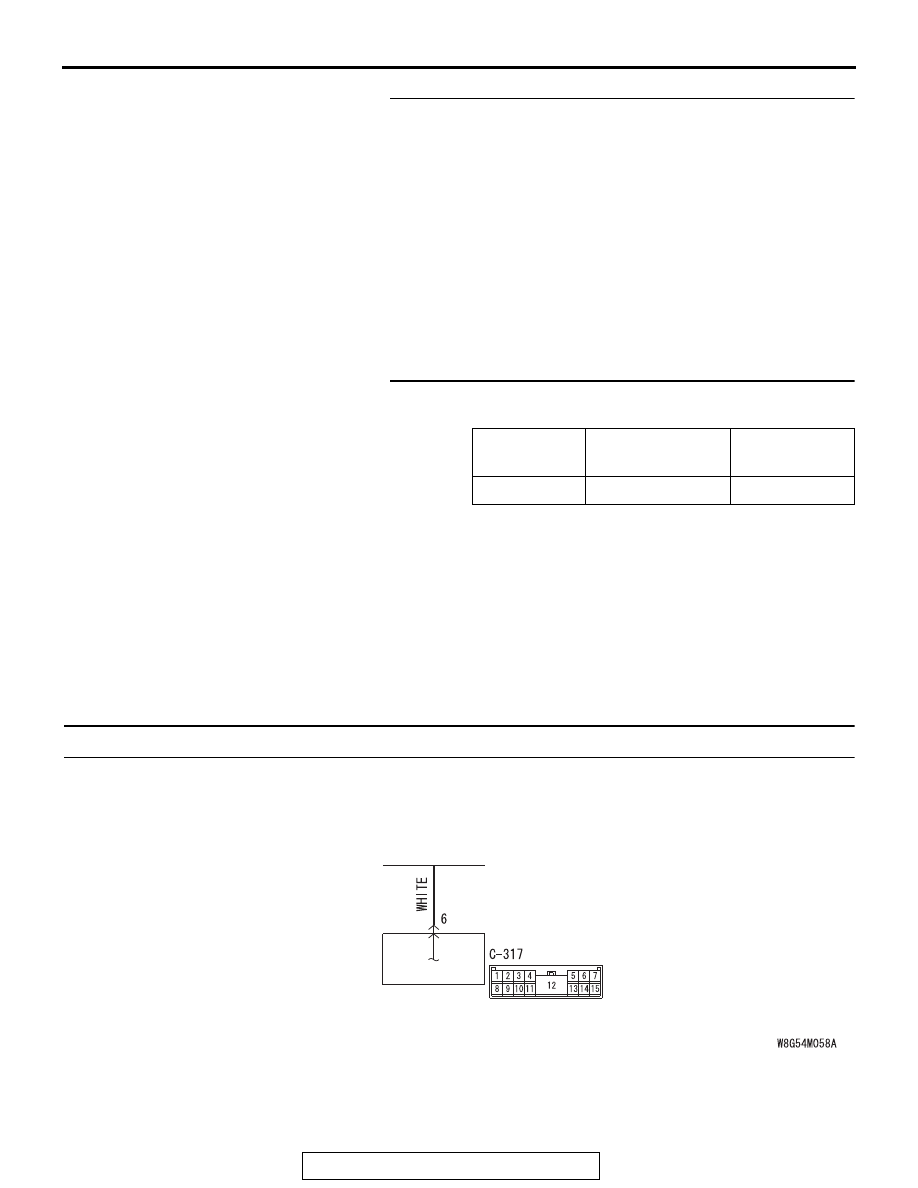
Ignition Switch (IG1) Input Circuit

ETACS-ECU

IGNITION
SWITCH (IG1)

ETACS

TSB Revision

CHASSIS ELECTRICAL

54A-790

.

TECHNICAL DESCRIPTION (COMMENT)

If there is an error to the ignition switch (IG1) input 
signal, or the IG1 relay inside the ETACS-ECU does 
not operate, the ignition switch (IG1) signal is no 
longer output to the communication line.

.

TROUBLESHOOTING HINTS

• The ignition switch may be defective

• The ETACS-ECU may be defective

• The fuse may be defective

• The wiring harness or connectors may have 

loose, corroded, or damaged terminals, or termi-
nals pushed back in the connector

DIAGNOSIS

Required Special Tools:

• MB991223: Harness Set

• MB992006: Extra Fine Probe

STEP 1. Check ETACS-ECU connector C-317 for loose, 
corroded or damaged terminals, or terminals pushed back 
in the connector.
Q: Is ETACS-ECU connector C-317 in good condition?

YES : Go to Step 2.
NO :  Repair or replace the damaged component(s). Refer 

to GROUP 00E, Harness Connector Inspection 

P.00E-2

. Check that the input signal of ignition switch 

(IG1) is normal.

STEP 2. Check the ignition switch (IG1) line of the power 
supply circuit to the ETACS-ECU. Measure the voltage at 
ETACS-ECU connector C-317.
(1) Measure by backprobing without disconnecting the 

connector.

(2) Turn the ignition switch to the "ON" position.
(3) Measure the voltage between the terminal No.6 and the 

ground.

• The voltage should measure approximately 12 volts 

(battery positive voltage).

Q: Is the measured voltage approximately 12 volts (battery 

positive voltage)?
YES : 
Go to Step 5.
NO :  Go to Step 3.

ACA02655AF

Connector: C-317

AC608254 DS

Harness side: C-317

ETACS

TSB Revision

CHASSIS ELECTRICAL

54A-791

STEP 3. Check the ignition switch.
Remove the ignition switch. Then check continuity between the 
switch terminal.

Q: Is the ignition switch in good condition?

YES : Go to Step 4.
NO :  Replace the ignition switch. Check that the input 

signal of ignition switch (IG1) is normal.

STEP 4. Check the wiring harness between ETACS-ECU 
connector C-317 (terminal 6) and the ignition switch (IG1).
Check the power supply line (IG1) for open circuit and short cir-
cuit.
Q: Is the wiring harness between ETACS-ECU connector 

C-317 (terminal 6) and ignition switch (IG1) in good 
condition?
YES : 
Go to Step 5.
NO :  The wiring harness may be damaged or the 

connector(s) may have loose, corroded or damaged 
terminals, or terminals pushed back in the connector. 
Repair the wiring harness as necessary. Check that 
the input signal of ignition switch (IG1) is normal.

STEP 5. Using scan tool MB991958, check data list. 

• Ignition switch: ON

OK: Normal condition is displayed.

Q: Is the check result normal?

YES : The trouble can be an intermittent malfunction (Refer 

to GROUP 00 

− How to use 

Troubleshooting/inspection Service Points, How to 
Cope with Intermittent Malfunction 

P.00-15

).

NO :  Refer to Inspection Procedure 2 "Defective power 

supply system of the ignition switch" 

P.54A-21

Ignition key 
position

Terminal 
number

Normal condition

LOCK

− 2, 1 − 4, 1 − 5, 

− 6

No continuity

ACC

− 6

Continuity exists (2 
ohms or less)

ON

− 2 − 4 − 6

Continuity exists (2 
ohms or less)

START

− 2 − 5

Continuity exists (2 
ohms or less)

Item No.

Item name

Normal 
condition

Item 254

IG voltage

12V

ETACS

TSB Revision

CHASSIS ELECTRICAL

54A-792

Inspection Procedure 3: ETACS-ECU does not receive any signal from the key reminder switch.

.

COMMENTS ON TROUBLE SYMPTOM

The key reminder switch input signal is used for the 
operation judgment of the functions below. If the sig-
nal is abnormal, these functions will not work.

• Ignition key reminder function

• Central door locking

• Keyless entry system

• KOS

• Ignition key cylinder illumination light

• Interior light

.

TROUBLESHOOTING HINTS

• The key reminder switch may be defective

• The ETACS-ECU may be defective

• The wiring harness or connectors may have 

loose, corroded, or damaged terminals, or termi-
nals pushed back in the connector

DIAGNOSIS

Required Special Tools:

• MB991223: Harness Set

• MB992006: Extra Fine Probe

ETACS-
ECU

KEY 
REMINDER 
SWITCH

WHEN REMOVING 
KEY:ON

Key Reminder Switch Input Circuit

AC702922AB

Connector: C-211

ACA02655AT

Connector: C-315


Content   ..  196  197  198  199   ..