Mitsubishi Outlander GS45X. Manual - part 193


  Index      Mitsubishi     Mitsubishi Outlander GS45X - service repair manual


Search            


Content   ..  191  192  193  194   ..


Mitsubishi Outlander GS45X. Manual - part 193


ETACS

TSB Revision

CHASSIS ELECTRICAL

54A-769

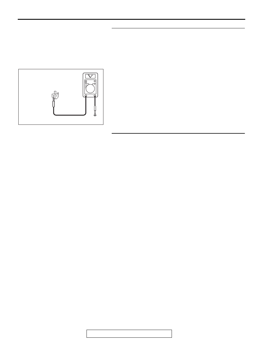
STEP 6. Check the battery power supply circuit to the 
ETACS-ECU. Measure the voltage at ETACS-ECU 
connector C-307.
(1) Disconnect ETACS-ECU connector C-307 and measure the 

voltage available at the wiring harness side of the 
connector.

(2) Turn the ignition switch to the "LOCK" (OFF) position.
(3) Measure the voltage between terminal 2 and ground.

• The voltage should measure approximately 12 volts 

(battery positive voltage).

Q: Is the measured voltage approximately 12 volts (battery 

positive voltage)?
YES : 
Go to Step 8.
NO :  Go to Step 7.

STEP 7. Check the wiring harness between ETACS-ECU 
connector C-307 (terminal 2) and the fusible link (36).
Check the power supply line for open circuit.
Q: Is the wiring harness between ETACS-ECU connector 

C-307 (terminal 2) and the fusible link (36) in good 
condition?
YES : 
No action is necessary and testing is complete.
NO :  The wiring harness may be damaged or the 

connector(s) may have loose, corroded or damaged 
terminals, or terminals pushed back in the connector. 
Repair the wiring harness as necessary.

AC608254 BF

Harness side: C-307

ETACS

TSB Revision

CHASSIS ELECTRICAL

54A-770

STEP 8. Using scan tool MB991958, check data list.
Check the power supply fuse voltage.

CAUTION

To prevent damage to scan tool MB991958, always turn the 
ignition switch to the "LOCK" (OFF) position before con-
necting or disconnecting scan tool MB991958.
(1) Connect scan tool MB991958. Refer to "How to connect the 

Scan Tool (M.U.T.-III) 

P.54A-730

."

(2) Check the ETACS data list.

• Turn the ignition switch to the "LOCK" (OFF) position.

Q: Does the scan tool MB991958 display the item "voltage 

sensing of IOD Line" is normal condition?
YES : 
Go to Step 9.
NO :  Replace the ETACS-ECU.

STEP 9. Recheck for diagnostic trouble code.
Check again if the DTC is set to the ETACS-ECU.
(1) Erase the DTC.
(2) Turn the ignition switch from "LOCK" (OFF) position to "ON" 

position.

(3) Check if DTC is set.
(4) Turn the ignition switch to the "LOCK" (OFF) position.
Q: Is the DTC set?

YES : Replace the ETACS-ECU.
NO :  The trouble can be an intermittent malfunction (Refer 

to GROUP 00, How to Cope with Intermittent 
Malfunction 

P.00-15

).

Item No.

Item name

Normal 
condition

Item 253

Voltage sensing 
of IOD Line

Approximately 
12 volts (battery 
positive voltage)

ZC501967

AC404789

AC702802

MB991824

MB991827

MB991910

Data link

connector

AB

ETACS

TSB Revision

CHASSIS ELECTRICAL

54A-771

DTC B222C: Coding incomplete

.

TROUBLE JUDGMENT

If the ETACS-ECU is in the initial state or the variant 
coding is incomplete, the ETACS-ECU sets DTC 
B222C.

.

TROUBLESHOOTING HINTS

• Variant code not written

• The ETACS-ECU may be defective.

DIAGNOSIS

Required Special Tools:

• MB991958: Scan Tool (M.U.T.-III Sub Assembly)

• MB991824: Vehicle Communication Interface (V.C.I.)

• MB991827: M.U.T.-III USB Cable

• MB991910: M.U.T.-III Main Harness A (Vehicles with 

CAN communication system)

Recheck for diagnostic trouble code.
Check again if the DTC is set to the ETACS-ECU.

CAUTION

To prevent damage to scan tool MB991958, always turn the 
ignition switch to the "LOCK" (OFF) position before con-
necting or disconnecting scan tool MB991958.
(1) Connect scan tool MB991958. Refer to "How to connect the 

Scan Tool (M.U.T.-III) 

P.54A-730

."

(2) Turn the ignition switch to the "ON" position.
(3) Perform the variant coding to the ETACS-ECU.
(4) Erase the DTC.
(5) Turn the ignition switch from "LOCK" (OFF) position to "ON" 

position.

(6) Check if DTC is set.
(7) Turn the ignition switch to the "LOCK" (OFF) position.
Q: Is the DTC set?

YES : Replace with the coded ETACS-ECU.
NO :  The diagnosis is complete.

ZC501967

AC404789

AC702802

MB991824

MB991827

MB991910

Data link

connector

AB

ETACS

TSB Revision

CHASSIS ELECTRICAL

54A-772

DTC B2206: Chassis number does not match

CAUTION

If DTC B2206 is set, always diagnose the CAN 
bus line.

.

TROUBLE JUDGMENT

If the registered chassis number is different from the 
chassis number transmitted on the CAN bus lines, 
the ETACS-ECU sets DTC B2206.

.

JUDGMENT CRITERIA

If the chassis number registered to ETACS-ECU and 
the chassis number on CAN bus lines do not match, 
the ETACS-ECU determines that a problem has 
occurred.

.

TROUBLESHOOTING HINTS

• Chassis number not written

• The ETACS-ECU may be defective.

• The engine control module may be defective.

• The CAN bus line may be defective.

DIAGNOSIS

Required Special Tools:

• MB991958: Scan Tool (M.U.T.-III Sub Assembly)

• MB991824: Vehicle Communication Interface (V.C.I.)

• MB991827: M.U.T.-III USB Cable

• MB991910: M.U.T.-III Main Harness A (Vehicles with 

CAN communication system)

STEP 1. Using scan tool MB991958, diagnose the CAN bus 
line.

CAUTION

To prevent damage to scan tool MB991958, always turn the 
ignition switch to the "LOCK" (OFF) position before con-
necting or disconnecting scan tool MB991958.
(1) Connect scan tool MB991958. Refer to "How to connect the 

Scan Tool (M.U.T.-III) 

P.54A-730

."

(2) Turn the ignition switch to the "ON" position.
(3) Diagnose the CAN bus line.
(4) Turn the ignition switch to the "LOCK" (OFF) position.
Q: Is the CAN bus line found to be normal?

YES : Go to Step 2.
NO :  Repair the CAN bus line. (Refer to GROUP 54C, 

Diagnosis 

P.54C-17

).

ZC501967

AC404789

AC702802

MB991824

MB991827

MB991910

Data link

connector

AB


Content   ..  191  192  193  194   ..