Mitsubishi Outlander GS45X. Manual - part 192
ETACS
TSB Revision
CHASSIS ELECTRICAL
54A-765
DTC U0331: ECU internal error
.
TROUBLE JUDGMENT
If the ETACS-ECU error counter value is detected to
be "255," DTC U0331 is set, and the ETACS-ECU is
reset. The DTC U0331 exists only as past trouble.
.
TROUBLESHOOTING HINTS
• The ETACS-ECU may be defective.
DIAGNOSIS
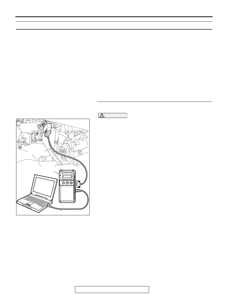
Required Special Tools:
• MB991958: Scan Tool (M.U.T.-III Sub Assembly)
• MB991824: Vehicle Communication Interface (V.C.I.)
• MB991827: M.U.T.-III USB Cable
• MB991910: M.U.T.-III Main Harness A (Vehicles with
CAN communication system)
Recheck for diagnostic trouble code.
Check again if the DTC is set to the ETACS-ECU.
CAUTION
To prevent damage to scan tool MB991958, always turn the
ignition switch to the "LOCK" (OFF) position before con-
necting or disconnecting scan tool MB991958.
(1) Connect scan tool MB991958. Refer to "How to connect the
Scan Tool (M.U.T.-III)
."
(2) Turn the ignition switch to the "ON" position.
(3) Erase the DTC.
(4) Turn the ignition switch from "LOCK" (OFF) position to "ON"
position.
(5) Check if DTC is set.
(6) Turn the ignition switch to the "LOCK" (OFF) position.
Q: Is the DTC set?
YES : Replace the ETACS-ECU.
NO : The diagnosis is complete.
ZC501967
AC404789
AC702802
MB991824
MB991827
MB991910
Data link
connector
AB