Mitsubishi Outlander GS45X. Manual - part 183
ETACS
TSB Revision
CHASSIS ELECTRICAL
54A-729
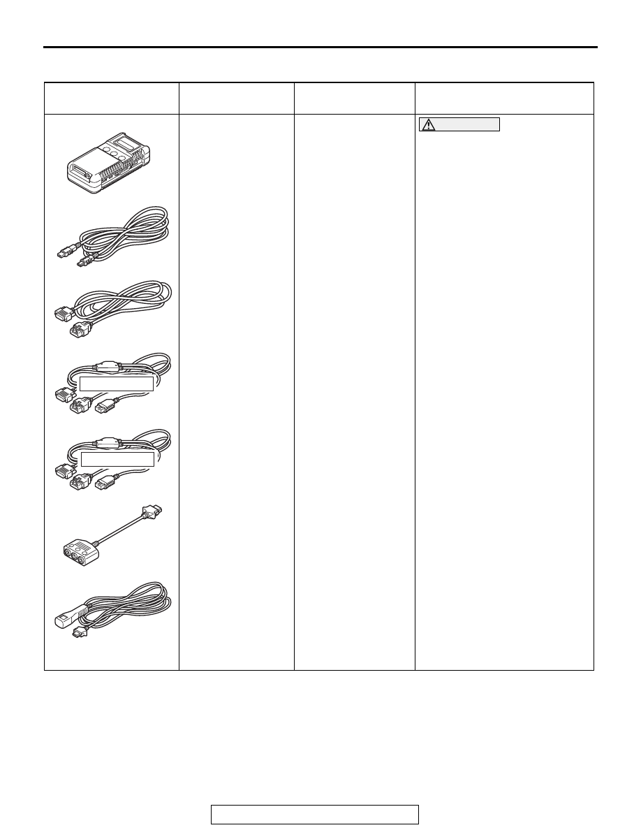
SPECIAL TOOL
M1545000600183
Tool
Tool number and
name
Supersession
Application
MB991958
a. MB991824
b. MB991827
c. MB991910
d. MB991911
e. MB991914
f. MB991825
g. MB991826
M.U.T.-III sub
assembly
a. Vehicle
communication
interface (V.C.I.)
b. M.U.T.-III USB
cable
c. M.U.T.-III main
harness A
(Vehicles with
CAN
communication
system)
d. M.U.T.-III main
harness B
(Vehicles without
CAN
communication
system)
e. M.U.T.-III main
harness C (for
Chrysler models
only)
f. M.U.T.-III
measurement
adapter
g. M.U.T.-III trigger
harness
MB991824-KIT
NOTE: G: MB991826
M.U.T.-III Trigger
Harness is not
necessary when
pushing V.C.I. ENTER
key.
CAUTION
M.U.T.-III main harness A
(MB991910) should be used.
M.U.T.-III main harness B and C
should not be used for this
vehicle.
ETACS-ECU check (Diagnostic
trouble code, service data)
MB991910
MB991826
MB991958
MB991911
MB991914
MB991824
MB991827
MB991825
DO NOT USE
a
b
c
d
e
f
g
DO NOT USE