Mitsubishi Outlander GS45X. Manual - part 177


  Index      Mitsubishi     Mitsubishi Outlander GS45X - service repair manual


Search            


Content   ..  175  176  177  178   ..


Mitsubishi Outlander GS45X. Manual - part 177


REAR DISPLAY

TSB Revision

CHASSIS ELECTRICAL

54A-705

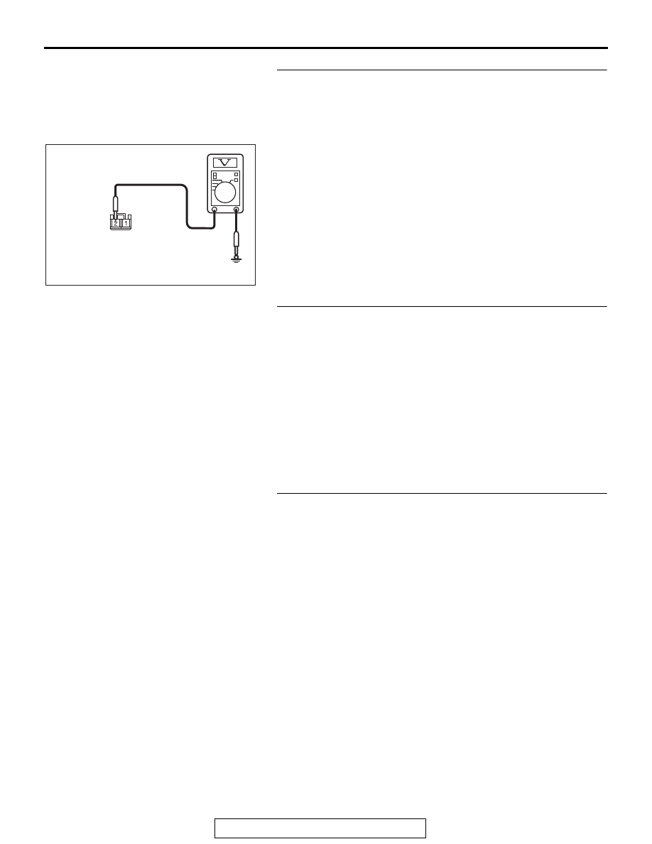
STEP 6. Check the power supply circuit to the ETACS-ECU. 
Measure the voltage at ETACS-ECU connector C-309.
(1) Disconnect ETACS-ECU connector C-309, and measure 

the voltage available at the wiring harness-side connector.

(2) Turn the ignition switch to the "ON" position.
(3) Measure the voltage between terminal 2 and ground.

OK: The voltage should measure approximately 12 
volts (battery positive voltage).

Q: Is the measured voltage approximately 12 volts (battery 

positive voltage)?
YES : 
Go to Step 8.
NO :  Go to Step 7.

STEP 7. Check the wiring harness between ETACS-ECU 
connector C-309 (terminal 2) and fusible link (37).

• Check the power supply line for open circuit and short cir-

cuit.

Q: Is the wiring harness between ETACS-ECU connector 

C-309 (terminal 2) and fusible link (37) in good 
condition?
YES : 
Go to Step 8.
NO :  The wiring harness may be damaged or the 

connector(s) may have loose, corroded or damaged 
terminals, or terminals pushed back in the connector. 
Repair the wiring harness as necessary. 

STEP 8. Check ETACS-ECU connector C-315 for loose, 
corroded or damaged terminals, or terminals pushed back 
in the connector.
Q: Is ETACS-ECU connector C-315 in good condition?

YES : Go to Step 9.
NO :  Repair or replace the damaged component(s). Refer 

to GROUP 00E, Harness Connector Inspection 

P.00E-2

.

AC702831AR

Harness side: C-309

REAR DISPLAY

TSB Revision

CHASSIS ELECTRICAL

54A-706

STEP 9. Check the power supply circuit to the ETACS-ECU. 
Measure the voltage at ETACS-ECU connector C-315.
(1) Disconnect the connector, and measure at the ETACS-ECU 

side connector.

(2) Turn the ignition switch to the "ACC" position.
(3) Measure voltage between terminal 9 and ground.

OK: The voltage should measure approximately 12 
volts (battery positive voltage).

Q: Is the measured voltage approximately 12 volts (battery 

positive voltage)?
YES : 
Go to Step 10.
NO :  Replace the ETACS-ECU.

STEP 10. Check the wiring harness between ETACS-ECU 
connector C-315 (terminal 9) and rear display unit 
connector D-06 (terminal 4).
NOTE: Also check intermediate connector D-123 for loose, cor-
roded, or damaged terminals, or terminals pushed back in the 
connector. If intermediate connector D-123 is damaged, repair 
or replace the connector as described in GROUP 00E, Harness 
Connector Inspection 

P.00E-2

.

• Check the power supply lines (ACC power supply) for open 

circuit and short circuit.

Q: Is the wiring harness between ETACS-ECU connector 

C-315 (terminal 9) and rear display unit connector D-06 
(terminal 4) in good condition?
YES : 
Go to Step 11.
NO :  The wiring harness may be damaged or the 

connector(s) may have loose, corroded or damaged 
terminals, or terminals pushed back in the connector. 
Repair the wiring harness as necessary. 

STEP 11. Check the ground circuit to the rear display unit. 
Measure the resistance at rear display unit connector D-06.
(1) Disconnect rear display unit connector D-06, and measure 

the resistance available at the wiring harness side of the 
connector.

(2) Measure the resistance between terminal 1 and ground.

OK: The resistance should be 2 ohms or less

Q: Is the measured resistance 2 ohms or less?

YES : Go to Step 13.
NO :  Go to Step 12.

AC702831AS

Component side: C-315

AC702818 BH

Harness side: D-06

REAR DISPLAY

TSB Revision

CHASSIS ELECTRICAL

54A-707

STEP 12. Check the wiring harness between rear display 
unit connector D-06 (terminal 1) and ground.
NOTE: Also check intermediate connector D-123 for loose, cor-
roded, or damaged terminals, or terminals pushed back in the 
connector. If intermediate connector D-123 is damaged, repair 
or replace the connector as described in GROUP 00E, Harness 
Connector Inspection 

P.00E-2

.

• Check the ground wires for open circuit.

Q: Is the wiring harness between rear display unit 

connector D-06 (terminal 1) and ground in good 
condition?
YES : 
The trouble can be an intermittent malfunction (Refer 

to GROUP 00, How to use 
Troubleshooting/inspection Service Points, How to 
Cope with Intermittent Malfunction 

P.00-15

).

NO :  The wiring harness may be damaged or the 

connector(s) may have loose, corroded or damaged 
terminals, or terminals pushed back in the connector. 
Repair the wiring harness as necessary. 

STEP 13. Check if the rear display unit displays normally.
Q: Does the rear display unit display normally?

YES : The trouble can be an intermittent malfunction (Refer 

to GROUP 00, How to use 
Troubleshooting/inspection Service Points, How to 
Cope with Intermittent Malfunction 

P.00-15

).

NO :  Replace the rear display unit.

Inspection Procedure 2: The rear display DVD player does not play the inserted DVD.

.

COMMENTS ON TROUBLE SYMPTOM

The DVD or the rear display unit may be defective.

.

PROBABLE CAUSES

• Defective DVD

• Malfunctions of rear display unit

DIAGNOSIS

STEP 1. Confirm the DVD.
Confirm that the DVD complies with the market specifications.
Q: Is the check result normal?

YES : Go to Step 2.
NO :  Use the DVD video disc made for the domestic use.

REAR DISPLAY

TSB Revision

CHASSIS ELECTRICAL

54A-708

STEP 2. Confirm that the DVD is inserted with its correct 
side facing up.
Confirm that the DVD is inserted with its correct side facing up.
Q: Is the check result normal?

YES : Go to Step 3.
NO :  Check the correct disc insertion direction, then 

reinsert the disc (if it is a single-sided disc, insert with 
the label facing upward).

STEP 3. Confirm the DVD video disk.
Confirm that the DVD is not contaminated or scratched.
Q: Is the check result normal?

YES : Go to Step 4.
NO :  Clean the disk or use a clean disk.

STEP 4. Retest the system
Check that the DVD is played normally when it is inserted.
Q: Is the check result normal?

YES : The procedure is complete.
NO :  Replace the rear display unit.

Inspection Procedure 3: The rear display displays the DVD picture, but the sound is not played.

.

COMMENTS ON TROUBLE SYMPTOM

The DVD or the rear display unit may be defective.

.

PROBABLE CAUSES

• Defective DVD

• Malfunctions of rear display unit

DIAGNOSIS

STEP 1. Confirm the DVD.
Check that the played DVD contains sound.
Q: Is the check result normal?

YES : Go to Step 2.
NO :  Use the DVD which contains sound.

STEP 2. Check of played back scene
Check that the played scene contains sound.
Q: Is the check result normal?

YES : Go to Step 3.
NO :  Play the scene with sounds, and check.

STEP 3. Check of playing method
Check whether the disc was played normally and not with spe-
cial playback (fast rewind, fast forward, slow, pause).
Q: Is the check result normal?

YES : Go to Step 4.
NO :  Check with the normal playback.


Content   ..  175  176  177  178   ..