Mitsubishi Outlander GS45X. Manual - part 1746


  Index      Mitsubishi     Mitsubishi Outlander GS45X - service repair manual


Search            


Content   ..  1744  1745  1746  1747   ..


Mitsubishi Outlander GS45X. Manual - part 1746


TRANSAXLE ASSEMBLY

TSB Revision

AUTOMATIC TRANSAXLE

23C-289

2. Fully push the torque converter into the transaxle side so 

that it does not remain on the engine side.

.

<<C>> TRANSAXLE MOUNTING BRACKET 
REMOVAL

1. Place a garage jack against the transaxle case with a piece 

of wood in between to support the engine and transaxle 
assembly.

2. Operate a garage jack so that the weight of the engine and 

transaxle assembly is not applied to the transaxle mounting 
insulator, and remove the transaxle mounting bracket.

.

<<D>> ENGINE ASSEMBLY HOLDING

CAUTION

The engine hanger plate (special tool: MB992208)should 
be secured by tightening bolts with the engine hanger 
plate to the specified torque (If the other bolts are used, 
the engine assembly may fall down when it is raised.)


Tightening torque: 22 

± 4 Nm (16 ± 2 ft-lb)

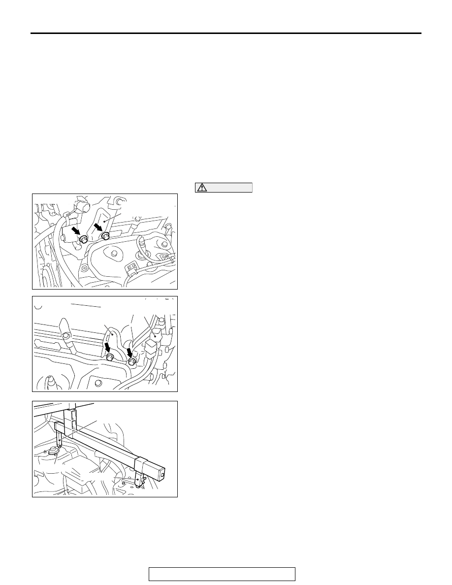
1. Remove the intake manifold plenum stay, rear on the right 

bank and the engine hanger on the left bank, and then install 
the engine hanger plate (Special tool: MB992208) to the 
place.

2. When engine hanger (Special tool: MB991928) is used

(1) Assemble the engine hanger (Special tool: MB991928). 

(Set the components below to the base hanger.)

• Slide bracket (HI)

• Foot x 2 (standard) (MB991932)

• Foot x 2 (short) (MB991933)

• Joint x 2 (90) (MB991930)

(2) Set the feet of the special tool as shown in the figure.

NOTE: Adjust the engine hanger balance by sliding the 
slide bracket (HI).

AC607864

AB

<Right bank>

Intake manifold
plenum stay, rear

AC607865

AB

<Left bank>

Engine hanger

Left bank heated oxygen
sensor connector

AC607801

AB

MB991930

MB991933

MB991932

TRANSAXLE ASSEMBLY

TSB Revision

AUTOMATIC TRANSAXLE

23C-290

(3)  Set the chains of the engine hanger (Special tool: 

MB991527) and the engine hanger balancer (Special 
tool: MB991454) to support the engine and transaxle 
assembly. Remove the garage jack and then remove the 
transaxle assembly upper part coupling bolts that have 
been loosened previously.

3.  When using engine mechanical hanger (Special tool: 

MB991895)

(1) Set the foot of the engine mechanical hanger (Special 

tool: MB991895) as shown in the figure.
NOTE: Slide the front foot of the engine mechanical 
hanger (Special tool: MB991895) to balance the engine 
hanger.

CAUTION

Place rag between the engine mechanical hanger (Special 
tool: MB991895) and the windshield to prevent the special 
tool from interfering with the windshield.

(2) Set the chains of the engine hanger (Special tool: 

MB991527) and the engine hanger balancer (Special 
tool: MB991454) to support the engine and transaxle 
assembly. Remove the garage jack and then remove the 
transaxle assembly upper part coupling bolts that have 
been loosened previously.

AC607802

AB

MB991928

MB991454

AC607803

AB

MB991895

AC607804

AB

AC607805

AB

MB991895

MB991454

TRANSAXLE ASSEMBLY

TSB Revision

AUTOMATIC TRANSAXLE

23C-291

INSTALLATION SERVICE POINTS

.

>>A<< TRANSAXLE ASSEMBLY INSTALLATION

Fully push the torque converter into the transaxle side, and 
then assemble the transaxle assembly to the engine.

.

>>B<< TRANSAXLE MOUNTING INSULATOR 
STOPPER INSTALLATION

Install the transaxle mounting insulator stopper as shown in the 
figure.

.

>>C<< TRANSAXLE CONTROL CABLE 
(TRANSAXLE SIDE) INSTALLATION

1. Move the selector lever and manual control lever to the "N" 

position.

2. Use the adjusting nut to tighten the transaxle control cable to 

the specified torque.

Tightening torque: 9.5 

± 3.5 Nm (84 ± 30 in-lb)

AC607806AB

Converter housing

Approximately 
13 mm

Torque converter

AC803110AB

Engine side

Transaxle mounting
insulator

Transaxle 
mounting
insulator 
stopper

Transaxle 
mounting
bracket

AC607760

AB

AC607760

Transaxle control cable

Adjusting nut

TRANSFER ASSEMBLY <AWD>

TSB Revision

AUTOMATIC TRANSAXLE

23C-292

TRANSFER ASSEMBLY <AWD>

REMOVAL AND INSTALLATION <VEHICLES WITH S-AWC>

M1231006000594

REMOVAL SERVICE POINT

.

<<A>> EXHAUST MANIFOLD BRACKET

CAUTION

Do not loosen the bolts other than shown.

Pre-removal and post-installation operation
• Under cover removal and installation (Refer to GROUP 51 

P.51-22

.)

• Transmission fluid draining and refilling (Refer to 

P.23C-265

.)

• Transfer oil draining and refilling (Refer to 

P.23C-272

.)

• Propeller shaft removal and installation (Refer to GROUP 

25 

P.25-7

.)

• Front axle crossmember assembly removal and installa-

tion (Refer to GROUP 32 

P.32-17

.)

• Drive shaft assembly <RH> removal and installation 

(Refer to GROUP 26, Drive Shaft Assembly 

P.26-23

.)

AC900535AC

1

2

4

69 ± 9 N·m
51 ± 6 ft-lb

69 ± 9 N·m
51 ± 6 ft-lb

8.5 ± 3.5 N·m
75 ± 30 in-lb

5

23 ± 3 N·m
17 ± 2 ft-lb

41 ± 10 N·m
30 ± 7 ft-lb

3

(Transmission fluid)

N

Removal steps 

1.

Heat protector

2.

Connector connection

<<

A

>>

3.

Exhaust manifold bracket

4.

Transfer assembly

5.

O-ring

Removal steps (Continued)

AC902800

AB

Exhaust manifold
bracket


Content   ..  1744  1745  1746  1747   ..